Three-dimensional scanning measurement device of robot, and working method
A measuring device and three-dimensional scanning technology, which is applied in the direction of manufacturing tools, metal processing equipment, grinding machine parts, etc., to eliminate the influence of leading dimensions, improve calibration efficiency, and improve accuracy
- Summary
- Abstract
- Description
- Claims
- Application Information
AI Technical Summary
Problems solved by technology
Method used
Image

Examples
Embodiment 1
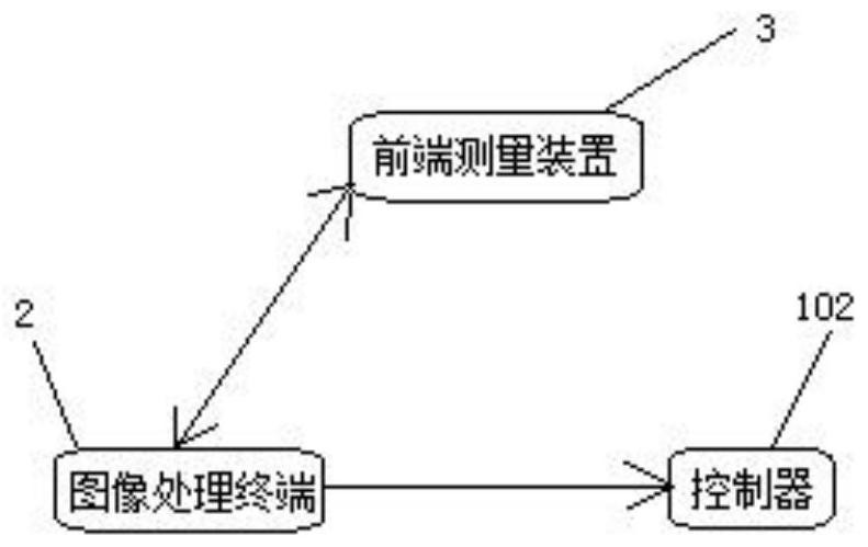
[0052] Such as Figure 4 As shown, the robot three-dimensional scanning measurement device includes measurement and calibration functions. When the image processing terminal 2 selects the measurement function, the robot three-dimensional scanning measurement device enters the measurement state according to the measurement method. The specific measurement method includes the following steps:
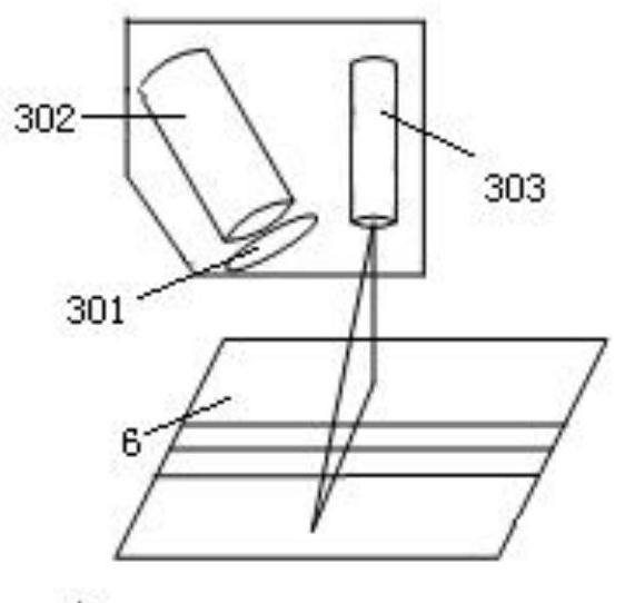
[0053] Step 1, target image collection, the camera 302 shoots and collects the target image containing the laser line, and transmits the target image to the image processing terminal 2 through Ethernet;
[0054] Step 2, image processing, image processing is performed on the target image in the image processing terminal 2, and the coordinates of the robot coordinate system are obtained. The image processing includes:
[0055] Step 2.1, image filtering, performing filtering processing on the target image;
[0056] Step 2.2, image threshold segmentation, using the maximum inter-class varian...
Embodiment 2
[0115] The robot three-dimensional scanning measurement device includes a measurement function, and the robot three-dimensional scanning measurement device enters the measurement state according to the measurement method. The specific measurement method includes the following steps:
[0116] Step 1, target image collection, the camera 302 shoots and collects the target image containing the laser line, and transmits the target image to the image processing terminal 2 through Ethernet;
[0117] Step 2, image processing, image processing is performed on the target image in the image processing terminal 2, and the coordinates of the robot coordinate system are obtained. The image processing includes:
[0118] Step 2.1, image filtering, performing filtering processing on the target image;
[0119] Step 2.2, image threshold segmentation, using the maximum inter-class variance method (OSTU) to dynamically set the threshold according to the background and laser lines in the target ima...
Embodiment 3
[0136] The robot three-dimensional scanning measurement device includes a measurement function and a calibration function, and the robot three-dimensional scanning measurement device enters the calibration state according to the calibration method,
[0137] The robot has a rotation axis, so the description of the actual object in space should also include its posture, that is, the orientation and posture of the object. figure 1 As shown, there is a world coordinate system {W} and another coordinate system {P} in the space, Indicates the value of each axis direction of the {P} coordinate system relative to the coordinate system {W}, then the attitude relationship of a point in {P} at {W} can be:
[0138]
[0139] Among them, r 11 ~ r 33 is the unit orthogonal rotation matrix, so Both the transpose matrix and the inverse matrix of are themselves.
[0140] Such as Figure 6 As shown, the conversion relationship between the various coordinate systems in the three-dimensi...
PUM
 Abstract
Description
Claims
Application Information
 - Generate Ideas
- Intellectual Property
- Life Sciences
- Materials
- Tech Scout
- Unparalleled Data Quality
- Higher Quality Content
- 60% Fewer Hallucinations
Browse by: Latest US Patents, China's latest patents, Technical Efficacy Thesaurus, Application Domain, Technology Topic, Popular Technical Reports.
© 2025 PatSnap. All rights reserved.Legal|Privacy policy|Modern Slavery Act Transparency Statement|Sitemap|About US| Contact US: help@patsnap.com