Three-boiler type municipal domestic waste incinerator air and flue gas system

A technology for urban domestic waste and incinerators, applied in the field of waste incineration treatment systems, can solve the problems of affecting the service life of the grate, hidden dangers of environmental pollution, and incomplete decomposition of odors.

Pending Publication Date: 2020-09-18
郑州东兴环保能源有限公司
View PDF0 Cites 0 Cited by
  • Summary
  • Abstract
  • Description
  • Claims
  • Application Information

AI Technical Summary

Problems solved by technology

[0002] The general process flow of the flue gas system of urban domestic waste incinerators is as follows: the primary fan extracts the odor from the garbage pit, and after being heated by the primary air preheater, it enters each air chamber under the grate, and then enters the incinerator through the air holes on the grate plate. The wind dries and supports the combustion of the garbage on the grate; the flue gas produced by the combustion of garbage enters the flue of the waste heat boiler, and is denitrated by the SNCR device; then flows through other flues of the waste heat boiler, and finally enters from the coal-saving outlet of the waste heat boiler Deacidification tower; the flue gas passes through the deacidification tower to remove the acid gas in the flue gas, and the flue gas passes through the activated carbon injection device arranged between the economizer outlet and the deacidification tower to absorb dioxins and heavy metals in the flue gas; then the flue gas The air enters the dust collector to filter the particulate matter in the flue gas; then the clean flue gas from the dust collector is heated by SGH steam and enters the SCR denitrification device, and the clean flue gas discharged up to the standard is discharged from the chimney to the atmosphere through the induced draft fan; but the existing domestic waste For the flue gas system of the incinerator, when the boiler is started in a cold state, due to the influence of the heat-resistant upper limit temperature of the grate material, the smoke temperature is generally selected to be started before 350°C ②The primary fan is used to cool the grate, otherwise the grate will expand unevenly, It causes the grate pieces to warp, which affects the service life of the grate. In severe cases, the furnace must be shut down for replacement; according to the research of Bai Liangcheng and other scholars, when the temperature of the flue gas in the furnace reaches 700 ° C, it stays for 0.5 seconds, which can prevent dioxin and odor complete decomposition of
Meet the flue gas emission requirements; when the boiler is started in a cold state, start before the flue temperature reaches 350°C ②The primary fan draws out the odor from the garbage pit and enters the furnace. According to the furnace temperature rise table, the furnace temperature rises from 350°C to 700°C , each time as long as 5-6 hours, during this period of time, the odor entering the boiler is not completely decomposed; the flue gas is only filtered by the dust collector and adsorbed by activated carbon, and then discharged from the chimney to the atmosphere through the induced draft fan, which has hidden dangers of environmental pollution

Method used


Image

  • Three-boiler type municipal domestic waste incinerator air and flue gas system
  • Three-boiler type municipal domestic waste incinerator air and flue gas system
  • Three-boiler type municipal domestic waste incinerator air and flue gas system

Examples


Embodiment 1

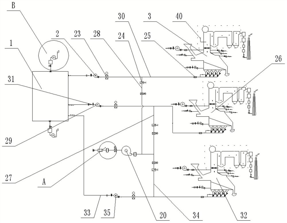
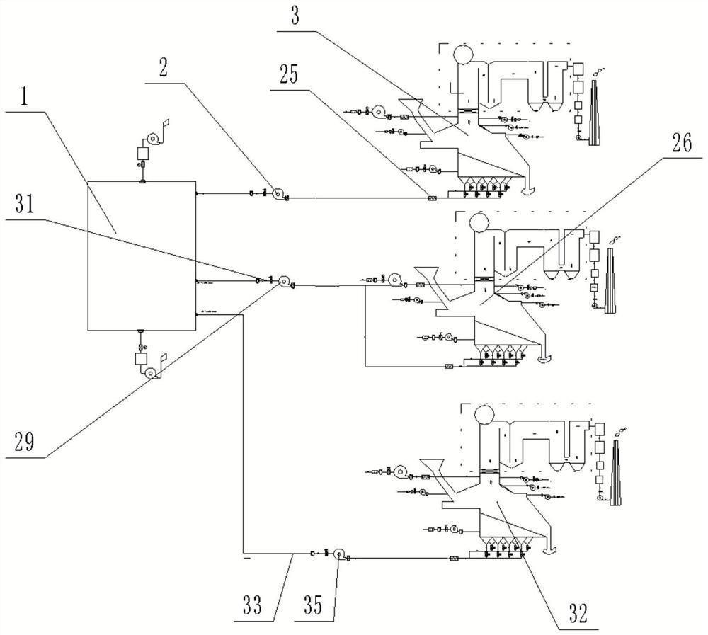
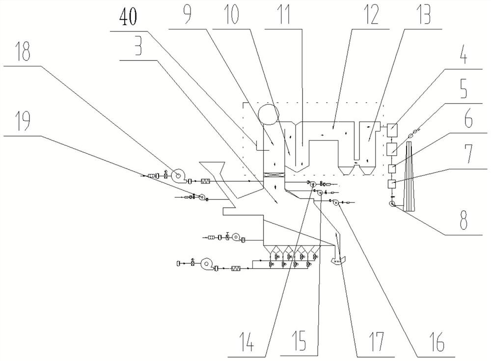
[0027] Such as Figure 1~5As shown, the air-smoke system of a one-pit three-furnace municipal solid waste incinerator includes a garbage storage pit 1, which is connected to a primary fan I2, a primary air preheater I25, and an incineration boiler I3 through a pipeline I30 in sequence; The pit is connected with the primary fan II, the primary air preheater II, and the incineration boiler II26 in turn through the pipeline II31; The deodorizing device inlet filter screen 39, the deodorizing device inlet electric door 36, the gac suction device 37 and the explosion-proof type deodorizing blower fan 38 connected successively, the deodorizing device I, the deodorizing device II are installed in the garbage storage pit 1 both sides, its The function is to start the deodorizing fan device when the garbage pit incinerator is completely out of operation, maintain the negative pressure of the garbage pit, and prevent the overflow of the garbage pit odor; the garbage storage pit is conne...


PUM


Abstract

The invention discloses a three-boiler type municipal domestic waste incinerator air and flue gas system, and relates to a waste incineration treatment system. The system comprises a waste storage pit; the waste storage pit is connected with a deodorization device I, a deodorization device II, a primary air blower I, a primary air pre-heater I, an incineration boiler I, a primary air blower II, aprimary air pre-heater II, an incineration boiler II, a primary air blower III, a primary air pre-heater III and an incineration boiler III through pipelines; a fresh air blower device is further connected onto the pipelines and is connected with the primary air pre-heater I and the primary air pre-heater II; air outlet isolation baffles are movably arranged on a fresh air outlet pipeline I and afresh air outlet pipeline II; mechanical fire grates are arranged at the bottom of the incineration boiler I, the bottom of the incineration boiler II and the bottom of the incineration boiler III; the top of the incineration boiler I, the top of the incineration boiler II and the top of the incineration boiler III are waste heat boilers; economizers are arranged at the tail ends of the waste heatboilers; and outlets of the economizers are connected with tail gas treatment devices. The system has the advantages of capability of improving the running reliability of a primary air system and increasing the economic benefit.

Description

technical field [0001] The invention relates to a garbage incineration treatment system, in particular to a one-pit three-furnace type urban domestic garbage incinerator air-smoke system. Background technique [0002] The general process flow of the flue gas system of urban domestic waste incinerators is as follows: the primary fan extracts the odor from the garbage pit, and after being heated by the primary air preheater, it enters each air chamber under the grate, and then enters the incinerator through the air holes on the grate plate. The wind dries and supports the combustion of the garbage on the grate; the flue gas produced by the combustion of garbage enters the flue of the waste heat boiler, and is denitrated by the SNCR device; then flows through other flues of the waste heat boiler, and finally enters from the coal-saving outlet of the waste heat boiler Deacidification tower; the flue gas passes through the deacidification tower to remove the acid gas in the flue ...

Claims


Application Information

Patent Timeline
IPC IPC(8): F23G5/00F23G5/44F23G5/50F23J15/02F23J15/08F23L1/00F23L5/02F22D1/20
CPCF22D1/20F23G5/006F23G5/44F23G5/50F23J15/022F23J15/08F23L1/00F23L5/02Y02E20/34
Inventor 景玉博张高辉姚喜恩刘展李伟砚杨留锋
Owner 郑州东兴环保能源有限公司
Why Eureka
Try Eureka