
Dedusting ash cooling ball forming production line

A production line and ash cooling technology, applied in the field of dust removal ash cooling ball forming production line, which can solve the problems of easy breakage and splitting, poor adhesion performance of dust removal ash cooling balls, etc.

Active Publication Date: 2020-09-22
CHONGQING ZHONGZHA METALLURGY RENEWABLE RESOURCESCO
View PDF11 Cites 2 Cited by
  • Summary
  • Abstract
  • Description
  • Claims
  • Application Information

AI Technical Summary

Problems solved by technology

[0004] The present invention intends to provide a dust removal ash cooling ball forming production line to solve the problem that the dust removal ash cooling ball produced by the existing dust removal ash cooling ball production line has poor bonding performance and is easy to break and split when falling from a high-level silo

Method used


Image

  • Dedusting ash cooling ball forming production line
  • Dedusting ash cooling ball forming production line
  • Dedusting ash cooling ball forming production line

Examples


Embodiment 1

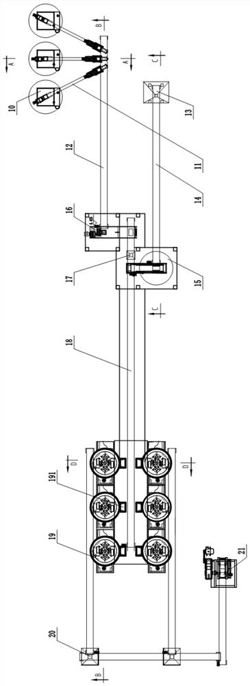
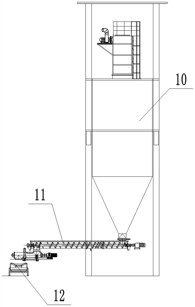
[0031] This embodiment is basically as figure 1 , image 3 Shown: Dedusting ash cooling ball forming production line, including wetting device, binder feeding device, iron-containing dust feeding system, dedusting ash feeding system, reaction kettle 19 and ball pressing machine 21 for pressing materials into balls. The dust removal ash feeding system is used to transport the dust removal ash to the wetting device, between the wetting device and the reactor 19, between the binder feeding device and the reactor 19, between the iron-containing dust feeding system and the reactor 19 A conveying device is provided. In this embodiment, the conveying device between the wetting device and the reactor 19, between the binder feeding device and the reactor 19, and between the iron-containing dust feeding system and the reactor 19 is the same The conveying device, the conveying device is the main belt conveyor 18, and the main belt conveyor 18 is used to transport materials such as dedus...

Embodiment 2

[0051] The difference between this embodiment and Embodiment 1 is that: Figure 11 As shown, in this embodiment, a vibrating screen is also provided to screen out unqualified dedusting ash chilled balls. The ball pressing machine 21 comprises a casing, which is provided with two ball-forming assemblies facing oppositely. Five tape conveyors), the vibrating screen is located at the bottom of the transport device away from the ball briquetting machine 21, and the vibrating screen is provided with a transport mechanism, and the transport mechanism returns the unqualified dust removal ash cooling ball to the briquetting machine 21. Setting up a vibrating screen can effectively screen out unqualified dedusting ash cooling balls (not pressed into a spherical shape) and improve the qualified rate of finished products.


PUM


Abstract

The invention belongs to the technical field of environment-friendly equipment in the metallurgical industry, and particularly relates to a dedusting ash cooling ball forming production line. The dedusting ash cooling ball forming production line comprises a wetting device, a binder feeding device, an iron-containing dust feeding system, a dedusting ash feeding system for conveying dedusting ash to the wetting device, a reaction kettle for enabling materials to be subjected to a magnesium cement reaction, and a ball press machine for pressing the materials into balls; delivery devices are arranged between the wetting device and the reaction kettle, between the binder feeding device and the reaction kettle and between the iron-containing dust feeding system and the reaction kettle; a conveying device is arranged between the reaction kettle and the ball press machine; and the wetting device is used for converting 30-60% of calcium oxide in the dedusting ash into calcium hydroxide. The wetting device is used for carrying out semi-digestion treatment on the dedusting ash, so that the finally obtained dedusting ash cooling balls are high in curing hardness and few in pores, and therefore, the dedusting ash cooling balls can bear the impact force falling from an overhead bunker and are not easy to crush.

Description

technical field [0001] The invention belongs to the technical field of environmental protection equipment in the metallurgical industry, and in particular relates to a dust removal ash cooling ball forming production line. Background technique [0002] In the field of steelmaking, dust removal (or steelmaking dust removal) can be roughly divided into two categories according to the needs and properties of dust removal settings: flue gas dust removal and environmental dust removal. Flue gas dust removal is the smoke exhaust process of steelmaking production The iron-containing dust generated in the environment, while the environmental dust removal dust is the dust generated in the environment of the production plant. [0003] Since the dedusting ash produced in the steelmaking process also contains a large amount of useful metal components, it is necessary to recycle the dedusting ash. In addition, because the dedusting ash from steelmaking has a high content of alkali metal ...

Claims


Application Information

Patent Timeline
IPC IPC(8): C22B1/248C22B7/02
CPCC22B1/2406C22B1/248C22B7/02Y02P10/20
Inventor 吴晓伟唐萍
Owner CHONGQING ZHONGZHA METALLURGY RENEWABLE RESOURCESCO
Learn More