A kind of non-woven fabric and its preparation system and preparation process
A technology for preparing systems and non-woven fabrics, which is applied in melt spinning, non-woven fabrics, rayon manufacturing, etc., can solve problems such as the inability to change the extrusion speed of the solution, and achieve the goal of avoiding clogging, avoiding coagulation, and enhancing fluidity Effect
- Summary
- Abstract
- Description
- Claims
- Application Information
AI Technical Summary
Problems solved by technology
Method used
Image
Examples
specific Embodiment approach 1
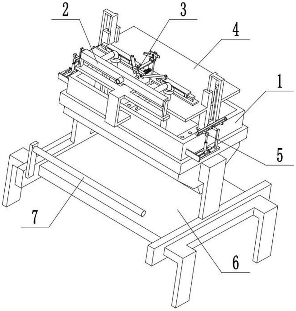
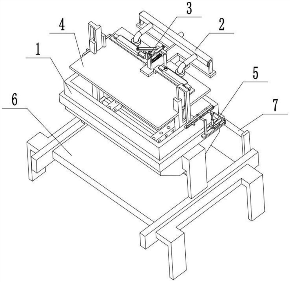
[0032] Combine below Figure 1-7Describe this embodiment, a non-woven fabric preparation system, including a meltblown die head piece 1, a blanking assembly 2, an anti-condensation mechanism 3, a material spraying platen 4, a speed adjustment mechanism 5, a receiving device 6, a collection roller 7, a high temperature Airflow generator and cooling airflow generator, the melt-blown die head piece 1 is arranged on the upper end of the receiving device 6, the collection roller 7 is arranged on one end of the receiver device 6, and the blanking assembly 2 is fixedly connected to the melt-blown die head part 1 Above, the anti-condensation mechanism 3 is set on the blanking assembly 2, the anti-condensation mechanism 3 is connected with the blanking assembly 2, the spraying pressure plate 4 is cooperatively connected to the melt blown die head part 1, and the spraying pressure plate 4 is located at the bottom of the anti-condensation mechanism 3 At the lower end, the injection press...
specific Embodiment approach 2
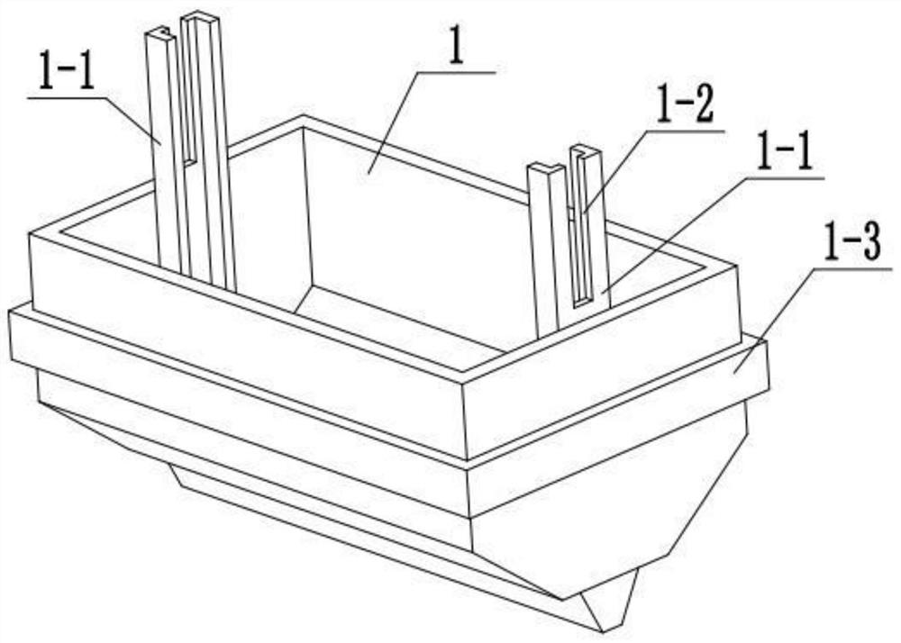
[0034] Combine below Figure 1-7 To illustrate this embodiment, the meltblown die head piece 1 is provided with a U-shaped sliding seat 1-1, an upper through groove 1-2 and an electric heating plate 1-3; two U-shaped sliding seats 1-1 are symmetrically fixed Connected to both ends of the melt-blown die head part 1, the upper ends of the two U-shaped slide seats 1-1 are respectively provided with an upper through groove 1-2, and the electric heating plate 1-3 is fixedly connected to the melt-blown die head part 1 The outer end of the outer end; the blanking assembly 2 is fixedly connected to the outer end of the meltblown die head part 1, and the spraying pressure plate 4 is slidably connected to the two U-shaped sliding seats 1-1. The electric heating plate 1-3 is connected to the power supply and turned on to heat the solution flowing into the melt-blown die part 1 to avoid condensation of the solution.
specific Embodiment approach 3
[0036] Combine below Figure 1-7 To illustrate this embodiment, the blanking assembly 2 includes a fixed frame 2-1, a catheter 2-2, a liquid inlet pipe 2-3, a shunt pipe 2-4, an infusion pipe 2-5, and a liquid discharge pipe 2- 6. The drain hole 2-7 and the gear 2-8; the fixed frame 2-1 is fixedly connected to the front end of the melt-blown die head 1, the catheter 2-2 is fixedly connected to the fixed frame 2-1, and the liquid inlet pipe 2-3 is fixedly connected and communicated in the middle of the fixed frame 2-1, two shunt tubes 2-4 are symmetrically fixedly connected and communicated with both ends of the catheter tube 2-2, and the upper ends of the two infusion tubes 2-5 are sealed separately Rotately connected to the two shunt tubes 2-4, the lower ends of the two infusion tubes 2-5 are respectively fixedly connected and connected to a drain tube 2-6, and the two drain tubes 2-6 are respectively provided with multiple drain tubes The holes 2-7 and the upper ends of the...
PUM
 Abstract
Description
Claims
Application Information
 - R&D
- Intellectual Property
- Life Sciences
- Materials
- Tech Scout
- Unparalleled Data Quality
- Higher Quality Content
- 60% Fewer Hallucinations
Browse by: Latest US Patents, China's latest patents, Technical Efficacy Thesaurus, Application Domain, Technology Topic, Popular Technical Reports.
© 2025 PatSnap. All rights reserved.Legal|Privacy policy|Modern Slavery Act Transparency Statement|Sitemap|About US| Contact US: help@patsnap.com


