Temperature-control pressure-resistant clamp device of high-flux visual micro-fluidic chip

A technology of microfluidic chip and fixture device, which is applied in the direction of supporting utensils, laboratory utensils, chemical instruments and methods, etc., which can solve the problems of poor sealing, difficult to meet, and small size of the feeding hole, and reduce the manufacturing cost. and maintenance costs, low manufacturing and maintenance costs, and strong liquid leakage prevention

Pending Publication Date: 2020-09-25
EAST CHINA UNIV OF SCI & TECH
View PDF2 Cites 5 Cited by
  • Summary
  • Abstract
  • Description
  • Claims
  • Application Information

AI Technical Summary

Problems solved by technology

However, the liquid inlet method in which the liquid inlet pipe is directly inserted into the chip feed hole leads to poor sealing of the feed hole.
In addition, repeated insertion and replacement of the liquid inlet pipe will cause chip material particles to enter the channel, causing blockage and prone to liquid leakage
However, the existing microfluidic chip fixture device does not have a heating device inside, and the range of the influent pressure that can withstand is small, so it is difficult to meet the requirements of experiments that require high pressure and temperature control.
In addition, the existing microfluidic chip clamps are small in size and size, and the chip area that can be clamped is limited, and high-throughput rapid response cannot be achieved.

Method used


Image

  • Temperature-control pressure-resistant clamp device of high-flux visual micro-fluidic chip
  • Temperature-control pressure-resistant clamp device of high-flux visual micro-fluidic chip
  • Temperature-control pressure-resistant clamp device of high-flux visual micro-fluidic chip

Examples


Embodiment Construction

[0036] The technical solutions of the present invention will be described in detail below through embodiments with reference to the accompanying drawings. It should be noted here that the descriptions of these embodiments are used to help understand the present invention, but are not intended to limit the present invention.

[0037] The term "and / or" in this article is just an association relationship describing associated objects, which means that there may be three relationships, for example, A and / or B, which can mean: A exists alone, B exists alone, and A and B exist simultaneously. In the three cases of B, the term " / and" in this article is to describe another associated object relationship, which means that there can be two relationships, for example, A / and B, which can mean: there is A alone, and there are two cases of A and B alone , In addition, the character " / " in this article generally indicates that the contextual objects are an "or" relationship.

[0038] accor...


PUM

PropertyMeasurementUnit
widthaaaaaaaaaa
thicknessaaaaaaaaaa

Abstract

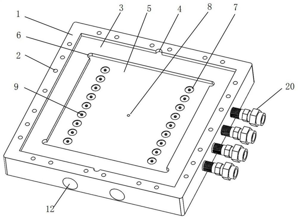
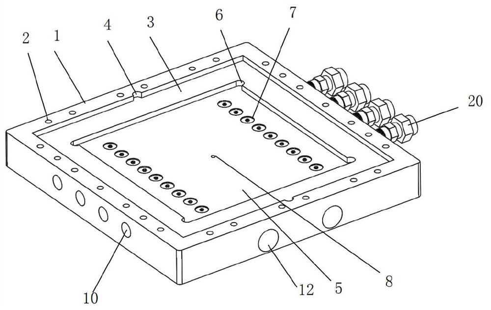
The invention discloses a temperature-control pressure-resistant fixture device of a high-flux visual micro-fluidic chip, which comprises a fixture main body, the fixture main body is in a rectangularblock shape, the upper surface of the fixture main body is provided with a fastening threaded hole and an extrusion groove, and the bottom of the extrusion groove is provided with a chip placing groove; a chip communicating groove is formed in the groove bottom of the chip placing groove, and a communicating hole is formed in the chip communicating groove; a clamp cover plate is arranged on the clamp main body, the clamp cover plate comprises a glass cover plate and a fastening cover plate, the glass plate is embedded in the extrusion groove, and the fastening cover plate is arranged on the clamp main body; and an infusion liquid outlet piece is arranged on the clamp main body and comprises an infusion piece and a liquid outlet piece. The device is low in manufacturing and maintenance cost, the micro-fluidic chip is convenient to replace, the capacity of preventing liquid from leaking is high, the experiment efficiency of the micro-fluidic chip is remarkably improved, the experiment temperature of the micro-fluidic chip can be adjusted, and in-situ observation and monitoring can be carried out in cooperation with an optical detection system.

Description

technical field [0001] The invention relates to the technical field of microfluidic chips, and more specifically, the invention relates to a temperature-controlling and pressure-resistant fixture device for a high-throughput visualized microfluidic chip. Background technique [0002] Microfluidic chip technology refers to the technology of using microchannels to process or manipulate microfluidic systems. It is an emerging interdisciplinary subject involving biology, chemistry, biomedicine, microelectronics, and new materials. It has the characteristics of miniaturization and integration. Compared with macro-scale experimental devices, microfluidic chip technology can significantly reduce sample consumption and improve reaction efficiency, so it has attracted widespread attention. The microfluidic chip fixture device uses its fixture to clamp and fix the chip. Through the design of the hole position on the fixture, it is aligned with the chip injection hole to ensure the com...

Claims


Application Information

Patent Timeline
Patent Type & Authority Applications(China)
IPC IPC(8): B01L9/00
CPCB01L9/527
Inventor 鲍博罗薇范启越邱俊杰赵双良朱维平钱旭红
Owner EAST CHINA UNIV OF SCI & TECH
Why Eureka
Try Eureka