Eureka AIR delivers breakthrough ideas for toughest innovation challenges, trusted by R&D personnel around the world.

Zener diode and manufacturing method thereof

A technology of Zener diode and manufacturing method, applied in semiconductor/solid-state device manufacturing, semiconductor device, electrical components and other directions, can solve the problems of weakening soft breakdown phenomenon and reducing the range of current variation, etc.

Active Publication Date: 2020-09-25
JOULWATT TECH INC LTD
View PDF7 Cites 3 Cited by
  • Summary
  • Abstract
  • Description
  • Claims
  • Application Information

AI Technical Summary

Problems solved by technology

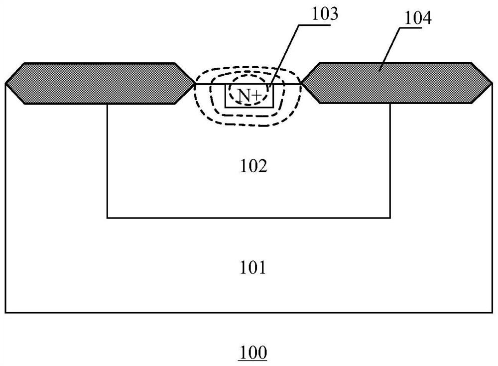
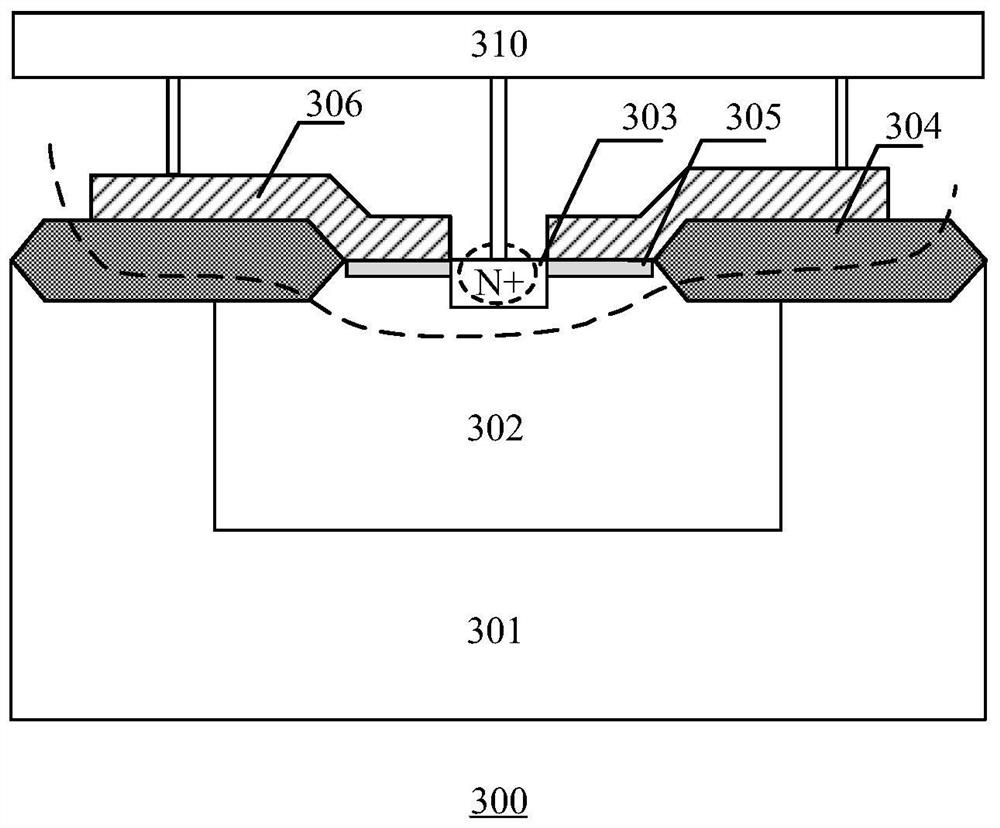
[0005] In the prior art, an improvement scheme based on this is to improve by adding an N-implantation region 205 in the Zener diode 200, such as figure 2 As shown, the introduction of the N-implantation region 205 can improve the radian of the curved surface junction to a certain extent, improve the equipotential line curvature of the edge of the N+ region 203, and try to maintain the same breakdown voltage in each region, but at the edge of the N-implantation region 205 The curved surface junction still exists, so the above scheme only weakens the soft breakdown phenomenon, so that the current variation range is reduced, and it cannot be completely avoided

Method used


Image

  • Zener diode and manufacturing method thereof
  • Zener diode and manufacturing method thereof
  • Zener diode and manufacturing method thereof

Examples


Embodiment Construction

[0043] Various embodiments of the invention will be described in more detail below with reference to the accompanying drawings. In the various drawings, the same elements are denoted by the same or similar reference numerals. For the sake of clarity, various parts in the drawings have not been drawn to scale. Also, some well-known parts may not be shown. For the sake of simplicity, the semiconductor structure obtained after several steps can be described in one figure.

[0044] When describing the structure of a device, when a layer or a region is referred to as being "on" or "over" another layer or another region, it may refer to being directly above another layer or another region, or between it and Other layers or regions are also included between another layer and another region. And, if the device is turned over, the layer, one region, will be "below" or "beneath" the other layer, another region.

[0045]If it is to describe the situation directly on another layer or ...


PUM


Abstract

The invention relates to the technical field of semiconductors, and provides a Zener diode and a manufacturing method thereof. The formed Zener diode comprises: a well region located on a substrate; afirst doped region located on the substrate and second doped regions ocated on the two sides of the first doped region respectively; field oxygen regions respectively positioned on one sides, far away from the first doped region, of the second doped regions, wherein the beak regions, close to one sides of the second doped regions, of the field oxygen regions are adjacent to the second doped regions; a polycrystalline silicon layer positioned above the field oxide regions and transversely extending to cover the second doped regions; and a first electrode in ohmic contact with the first doped region and the polycrystalline silicon layer, and a second electrode in ohmic contact with the substrate. According to the invention, the equipotential of the PN junction formed by the second doped region, the first doped region and the well region on the side surface of the second doped region is adjusted through the polycrystalline silicon layer positioned above the field oxide region and transversely extending to cover the upper surface of the second doped region, so that the breakdown voltage of the PN junction at each position is stabilized.

Description

technical field [0001] The invention relates to the field of semiconductors, in particular to a Zener diode and a manufacturing method thereof. Background technique [0002] A diode is an electronic component with a PN junction as its core. When its negative pole voltage is higher than its positive pole, it is called reverse bias. The reverse saturation current of a reverse biased diode is very small, but when the reverse bias voltage increases to a certain value, the reverse current It will increase sharply. This phenomenon is called the reverse breakdown of the diode. The reverse breakdown voltage (that is, the stable voltage) of the diode is very stable. Using this characteristic, a zener that works exclusively in the reverse breakdown state can be obtained. diode. The core part of the Zener diode is composed of P-region and N+ region (or P+ region and N-region), where "-" indicates that the doping concentration of this region is low, and "+" indicates that the doping co...

Claims


Application Information

Patent Timeline
IPC IPC(8): H01L29/866H01L29/06H01L21/329
CPCH01L29/866H01L29/0619H01L29/66106
Inventor 韩广涛蒋盛烽
Owner JOULWATT TECH INC LTD
Why Eureka
Eureka Blog
Learn More