Heating device

A heating device and technology to be heated, applied in electric heating devices, ohmic resistance heating, electrical components, etc., can solve the problems of temperature-sensitive plastics, shortened equipment life, low service life, etc., to achieve fast heat transfer speed, improve The effect of heat transfer efficiency and improved service life

Pending Publication Date: 2020-09-25
耀能(上海)节能科技股份有限公司
View PDF5 Cites 2 Cited by
  • Summary
  • Abstract
  • Description
  • Claims
  • Application Information

AI Technical Summary

Problems solved by technology

[0004] (1) The heat loss is large. The heating used in the existing asphalt machine is made of resistance wire. The inner and outer sides of the ring generate heat. Dissipated into the air, causing loss and waste of electric energy;
[0005] (2) Ambient temperature rise: due to a large amount of heat loss, the ambient temperature rises, especially in summer, which has a great impact on the production environment. The on-site working temperature exceeds 45°C. Some enterprises have to use air conditioners to reduce the temperature, which in turn causes energy consumption. time waste;
[0006] (3) Short service life and large amount of maintenance: due to the use of resistance wire for heating, the heating temperature is as high as 300°C, the resistance wire is easy to burn out due to high temperature aging and deformation, and it is not easy to replace after burning out. The service life of commonly used electric heating coils is about half a year. , often affects production, so the maintenance workload is relatively large;
[0007] (4) The power density is low, and it cannot be adapted to some occasions that require higher temperature;
[0008] (5) The temperature control accuracy is reduced, the temperature is easy to overshoot by more than 10°C, and the temperature control is inaccurate
However, if it is used in a system above 200 degrees, the temperature is easy to overshoot by more than 15 degrees, so it is not suitable for temperature-sensitive plastics
[0015] Therefore, the heating device of the resistance electric heating coil in the prior art has high energy consumption, poor temperature control accuracy, and low service life, while the heating device of electromagnetic induction heating has a good energy-saving effect, but it also has many problems. Disadvantages: 1) The electromagnetic radiation intensity of electromagnetic heating is still large, which may endanger human health; 2) There is harmonic pollution to the power grid, which distorts the voltage and current waveforms of the power grid, resulting in increased power loss of the power grid, shortened equipment life and Unsafe operation; 3) short service life

Method used


Image

  • Heating device
  • Heating device
  • Heating device

Examples


Embodiment 1

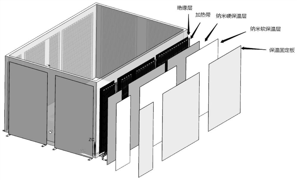
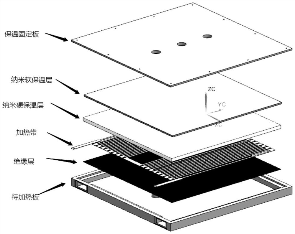
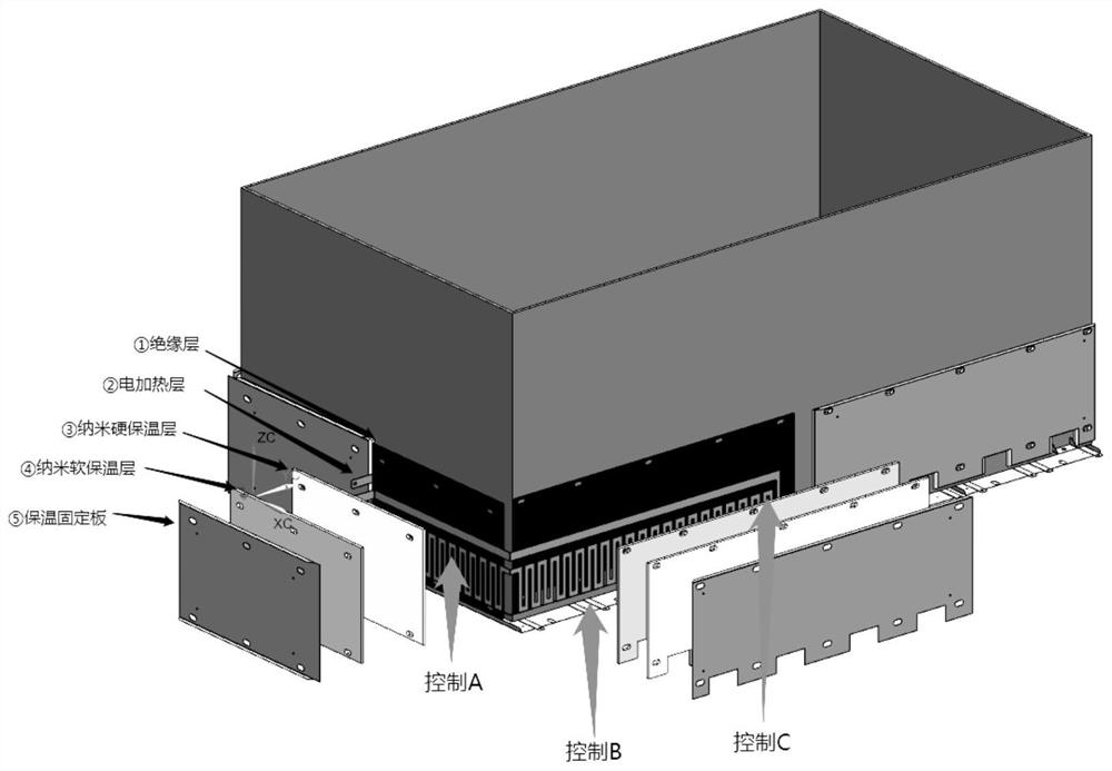
[0057] A heating device, in order to visualize the image, the structure of each layer of heating is split and displayed (for details, see Figure 2 to Figure 4 ), the heating device includes an object to be heated 200, an insulating layer 201, a heating assembly 202, a nano-hard thermal insulation layer 203, a nano-soft thermal insulation layer 204, and a thermal insulation fixing plate 205. Heating object 200, insulation layer 201, heating assembly 202, nanometer hard insulation layer 203, nanometer soft insulation layer 204, insulation fixing plate 205, insulation layer 201 is positioned on the object to be heated 200 and arranges object to be heated 200 side by side, heating assembly 202 The insulation layer 201 is arranged side by side on the insulating layer 201, the nano-hard insulation layer 203 is located on the heating assembly 202 and the heating assembly 202 is arranged side by side, and the nano-soft insulation layer 204 is located on the nano-hard insulation layer ...

Embodiment 2

[0061] A heating device, in order to visualize the image, the structure of each layer of heating is split and displayed. For details, see Figure 2 to Figure 4 . The heating device includes an object to be heated 200, an insulating layer 201, a heating assembly 202, a nano-hard insulation layer 203, a nano-soft insulation layer 204 and a fixed plate 205 for heat preservation. , insulation layer 201, heating assembly 202, nanometer hard insulation layer 203, nanometer soft insulation layer 204, insulation fixing plate 205, insulation layer 201 is positioned on the object to be heated 200 and arranges the object to be heated 200 side by side, and heating assembly 202 is positioned at insulation layer The upper 201 arranges the insulating layer 201 in parallel, the nano hard insulation layer 203 is located on the heating assembly 202 and arranges the heating assembly 202 in parallel, the nano soft insulation layer 204 is located on the nano hard insulation layer 203 and arranges ...

Embodiment 3

[0069] A heating device, in order to visualize the image, the structure of each layer of heating is split and displayed. For details, see Figure 2 to Figure 4 . The heating device includes an object to be heated 200, an insulating layer 201, a heating assembly 202, a nano-hard insulation layer 203, a nano-soft insulation layer 204 and a fixed plate 205 for heat preservation. , insulation layer 201, heating assembly 202, nanometer hard insulation layer 203, nanometer soft insulation layer 204, insulation fixing plate 205, insulation layer 201 is positioned on the object to be heated 200 and arranges the object to be heated 200 side by side, and heating assembly 202 is positioned at insulation layer The upper 201 arranges the insulating layer 201 in parallel, the nano hard insulation layer 203 is located on the heating assembly 202 and arranges the heating assembly 202 in parallel, the nano soft insulation layer 204 is located on the nano hard insulation layer 203 and arranges ...


PUM

PropertyMeasurementUnit
Thicknessaaaaaaaaaa
Thicknessaaaaaaaaaa

Abstract

The invention discloses a heating device. The device comprises an insulating layer, a heating assembly, a hard heat preservation layer and a soft heat preservation layer; the insulating layer, the heating assembly, the hard insulating layer, the soft insulating layer and the heat preservation shell are sequentially arranged from the inner layer to the outer layer; the heating assembly is located on the plane of the insulating layer arranged on the insulating layer side by side; the heat preservation layer is located on the heating assembly and arranged on the heating assembly side by side; andthe heat preservation shell is located on the heat preservation layer and covers the heat preservation layer. The heating device has a good energy-saving effect and is used for industrial heating, such as heating of an asphalt machine, a lead melting machine, a pulp paper electric heating plate, an industrial square pipeline and a square plane box body of an extruder.

Description

technical field [0001] The invention provides a heating device, especially related to industrial heating, such as pulp and paper electric heating plate, electric heating of square tank pool, industrial square and rectangular pipes and all irregular plane surfaces to be heated. Background technique [0002] At present, most asphalt machines and lead melting machines on the market still use resistance electric heating tubes, which generate heat based on the thermal effect of current, that is, when the current passes through the conductor, the resistance of the conductor hinders the current, and the current needs to To overcome the resistance of the conductor to do work, it converts electrical energy into heat energy and transmits it through conduction. Therefore, the inner wall of the heating tube must be in reliable contact with the outer wall of the box to transfer heat to the box. The outer wall of the heating tube Most of the heat is lost to the air, resulting in a decreas...

Claims


Application Information

Patent Timeline
IPC IPC(8): H05B3/28
CPCH05B3/28
Inventor 董文利
Owner 耀能(上海)节能科技股份有限公司
Why Eureka
Try Eureka