
Scanning type circuit board welding spot pseudo soldering automatic detection system and detection method

An automatic detection and detection method technology, applied in the direction of material defect testing, etc., can solve problems such as danger and solder joint failure, and achieve the effects of simple operation, convenient repair and high detection efficiency

Active Publication Date: 2020-10-02
HARBIN INST OF TECH
View PDF6 Cites 4 Cited by
  • Summary
  • Abstract
  • Description
  • Claims
  • Application Information

AI Technical Summary

Problems solved by technology

For solder joints, this method may cause some serious defect solder joints to fail (disconnect), and play a role in screening, but it is also very easy to cause the original tiny defects in some solder joints to expand into dangerous serious defects. The result outweighs the gain

Method used


Image

  • Scanning type circuit board welding spot pseudo soldering automatic detection system and detection method
  • Scanning type circuit board welding spot pseudo soldering automatic detection system and detection method
  • Scanning type circuit board welding spot pseudo soldering automatic detection system and detection method

Examples


specific Embodiment approach 1

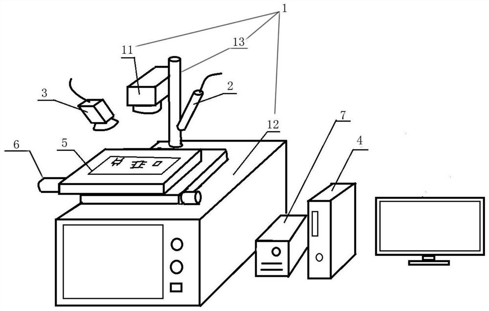
[0055] A scanning type circuit board solder joint virtual welding automatic detection system includes a galvanometer scanning laser 1, a digital optical microscope 2, an infrared thermal imager 3 and a computer 4, and the galvanometer scanning laser 1 includes a laser head 11 and a system Platform 12, the laser head 11 is fixed directly above the system platform 12 by a support rod 13 and is electrically connected with the system platform 12, and the infrared thermal imager 3 and the digital optical microscope 2 are respectively located on both sides of the laser head 11, so The field of view of the infrared thermal imager 3 and the digital optical microscope 2 overlaps and is positioned at the scanning range of the laser head 11 on the circuit board 5 to be tested, and the signal output end of the infrared thermal imager 3 is electrically connected to the signal input end of the computer 4 , the image signal output end of the digital optical microscope 2 is electrically connec...

specific Embodiment approach 2

[0059] The detection method of the scanning circuit board solder joint virtual welding automatic detection system described in the specific embodiment 1 includes the following steps:

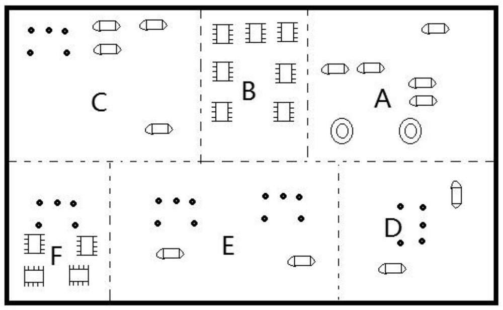
[0060] Step 1. Set and save the detection area solder spot scanning template in the system platform 12 of the galvanometer scanning laser 1;

[0061] Step 2, setting and saving the detection laser parameters in the system platform 12 of the galvanometer scanning laser 1;

[0062] Step 3: Set the temperature measurement template of the temperature measurement area for each solder joint in the detection area in the infrared thermal imager 3 and save it;

[0063] Step 4. Set and save the temperature measurement threshold for each solder joint in the detection area in the infrared thermal imager 3;

[0064] Step 5: Fix the circuit board 5 to be tested on the system platform 12 and below the laser head 11, fix it with a positioning fixture, start the vibrating mirror scanning laser 1, and the emitte...

specific Embodiment approach 3

[0073] The detection method of the scanning circuit board solder joint virtual welding automatic detection system described in the specific embodiment 1 includes the following steps:

[0074] Step 1, setting a scanning template for solder joints in the detection area in the system platform 12 of the galvanometer scanning laser 1;

[0075] Step 2, setting detection laser parameters in the system platform 12 of the galvanometer type scanning laser 1;

[0076] Step 3. Set the temperature measurement area for each solder joint in the detection area in the infrared thermal imager 3 and save the temperature measurement template;

[0077] Step 4. Set the temperature measurement threshold for each solder joint in the detection area in the infrared thermal imager 3;

[0078] Step 5: Fix the circuit board 5 to be tested on the system platform 12 and below the laser head 11, fix it with a positioning fixture, start the vibrating mirror scanning laser 1, and the emitted laser automatical...


PUM


Abstract

The invention discloses a scanning type circuit board welding spot pseudo soldering automatic detection system and detection method. The invention belongs to the technical field of printed circuit board welding spot quality offline detection. The specific scheme is as follows: the scanning type circuit board welding spot pseudo soldering automatic detection system comprises a galvanometer type scanning laser, a digital optical microscope, a thermal infrared imager and a computer; the galvanometer type scanning laser comprises a laser head and a system platform, wherein the laser head is arranged above the system platform and is electrically connected with the system platform; the thermal infrared imager and the digital optical microscope are respectively positioned beside the laser head; the visual fields of the thermal infrared imager and the digital optical microscope are overlapped and positioned within the scanning range of the laser head on the circuit board to be tested; the thermal infrared imager is electrically connected with the computer; and the digital optical microscope is electrically connected with the computer or the system platform. According to the invention, theindustry traditional problem that pseudo soldering of circuit board welding spots is difficult to detect is solved in a breakthrough manner, and the system has the characteristics of simple operation,automation and intellectualization and wide market prospect.

Description

technical field [0001] The invention belongs to the technical field of off-line detection of solder joint quality of printed circuit boards, and in particular relates to a scanning type automatic detection system and detection method for solder joints of printed circuit boards. Background technique [0002] Welding of solder joints is a common problem in the production process of printed circuit boards, and its causes are very complicated, and it is difficult to eradicate through the adjustment of the production process. Studies have shown that weak solder joints are one of the main causes of early failure in electronic products, accounting for up to 50%. [0003] The existing detection technologies mainly include automatic optical inspection (AOI), automatic X-ray inspection (AXI) and temperature shock test. [0004] Automatic optical inspection (AOI) technology is to take the image of circuit board components by CCD camera, and use software to compare it with the qualifie...

Claims


Application Information

Patent Timeline
Patent Type & Authority Applications(China)
IPC IPC(8): G01N25/72
CPCG01N25/72
Inventor 孔令超郑振张威刘威安荣
Owner HARBIN INST OF TECH
Learn More