Circuit and method for detecting overvoltage breakdown characteristics of IGBT
A technology for breakdown characteristics and testing circuits, which is used in circuits for detecting IGBT turn-off steady-state overvoltage breakdown characteristics, and in the field of IGBT overvoltage breakdown detection circuits, which can solve overvoltage breakdown, device failure, device breakdown, etc. problems to avoid secondary failures
- Summary
- Abstract
- Description
- Claims
- Application Information
AI Technical Summary
Problems solved by technology
Method used
Image

Examples
Embodiment 1
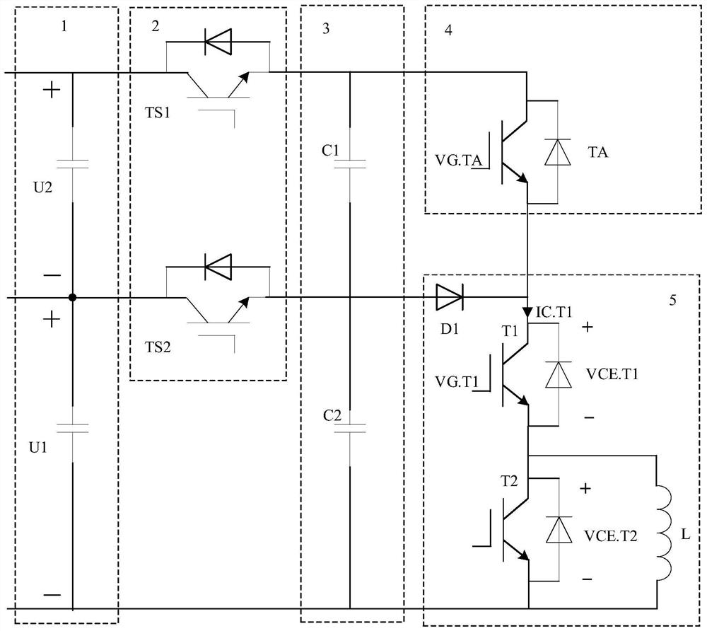
[0033] figure 1 A structural block diagram of the overvoltage breakdown detection circuit for the IGBT turn-off steady state provided by the present invention is given. The detection circuit includes: a DC bus power supply 1, a solid state circuit breaker 2, an energy storage capacitor 3, a step-up power electronic switch 4, and a double pulse test circuit 5.
[0034] The DC bus power supply is used to provide a stable DC voltage to the overvoltage detection circuit, including the DC power supply U1 of the conventional double pulse circuit and the overvoltage power supply U2 used to increase the collector-emitter voltage of the IGBT to be tested for a short time; the DC power supply U1 and the overvoltage The piezoelectric power supply U2 is connected in series; the voltages of the DC power supply U1 and the overvoltage power supply U2 are respectively stored by large-capacity capacitors to ensure that the bus voltage remains basically unchanged after multiple overvoltage dete...
Embodiment 2
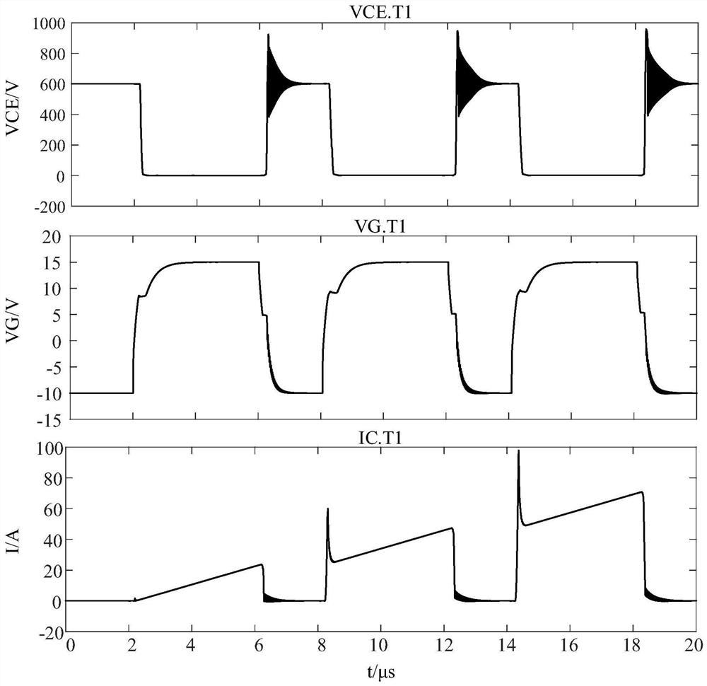
[0042] This example is based on figure 2 As shown in the output waveform of the IGBT, this embodiment adopts the IGBT module test, the module is composed of IGBT T1, IGBT T2 and its driver, IGBT T1, IGBT T2 are the same device, and the IGBT to be tested in the present invention is described in detail. A method for detecting overvoltage breakdown in a steady state, the method comprising,
[0043] Detect the collector voltage of IGBT T2;
[0044] Turn on the IGBT T1 to be tested that is not connected in parallel with the load inductance L, so that the IGBT T2 to be tested bears the voltage of the DC power supply U1;
[0045] After the IGBT T1 to be tested is fully turned on, turn on the power device TA with a narrow pulse;
[0046] When the power device TA is turned on, the IGBT T2 to be tested bears the sum of the voltage of the DC power supply U1 and the overvoltage power supply U2, and the IGBT T2 to be tested bears an overvoltage;
[0047] After the power device TA is tu...
Embodiment 3
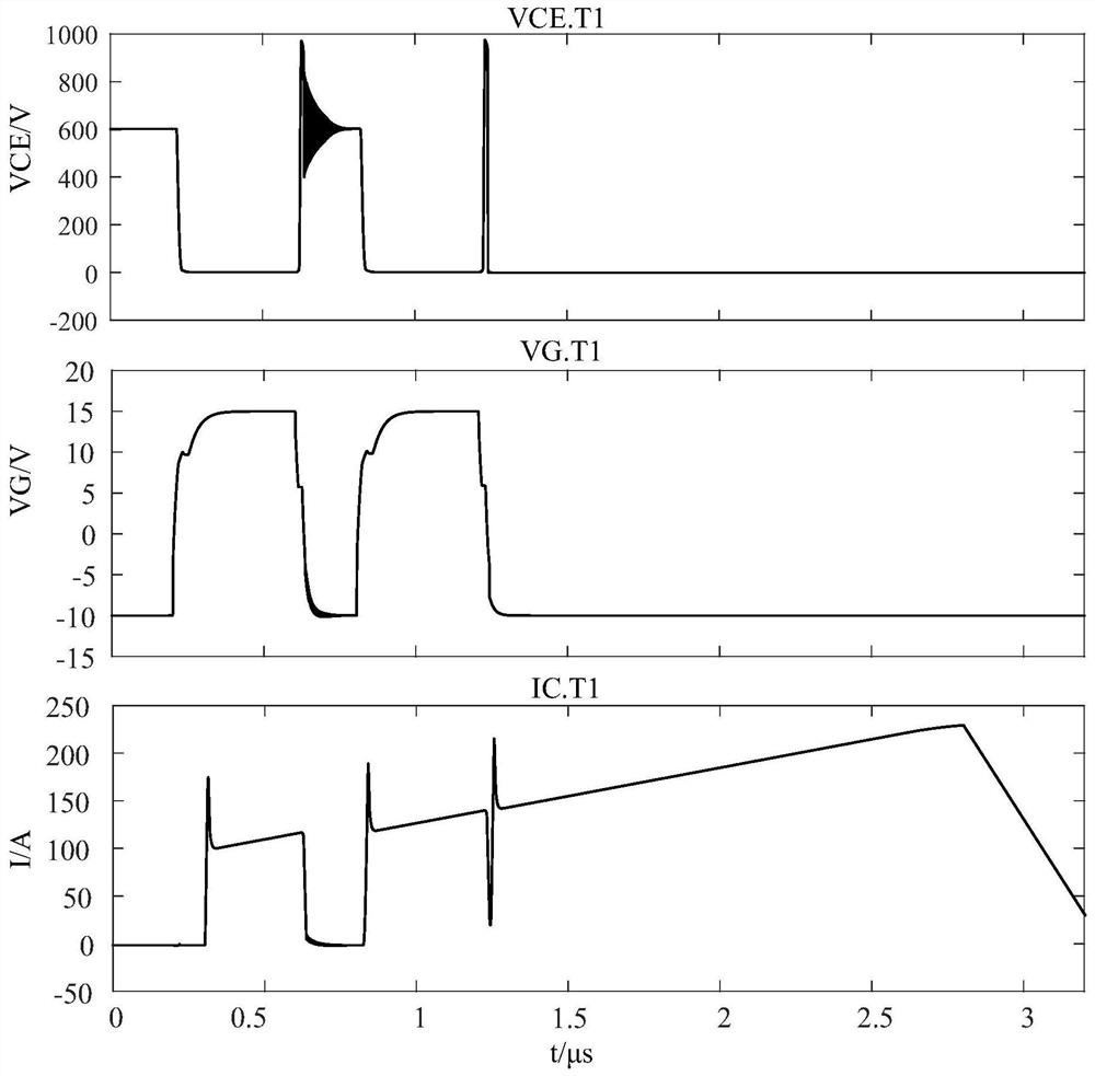
[0050] This embodiment is based on figure 2 The output waveform of the shown IGBT, the present embodiment adopts IGBT module test, and this module is made up of IGBT T1, IGBT T2 and its driver; A detection method for transient overvoltage breakdown, the method includes detecting the collector voltage of the IGBT T1;
[0051] Replace the clamping diode D1 with a conductor with higher stray inductance, and turn on the IGBT1 pulse to be tested that is not connected in parallel with the load inductance L. Large, the IGBTT1 under test will withstand too high breakdown voltage.
[0052] According to the specific application of the above method: the detection object is the IGBTT1 to be tested; replace the clamp diode D1 with a conductor with higher stray inductance, the voltage of the DC power supply U1 is 600V, set the IGBTT1 to be tested so that the turn-on time is 4 μs, and the turn-off time is 4 μs. The pulse of 2μs runs continuously. During the conduction process, the collect...
PUM
 Abstract
Description
Claims
Application Information
 - R&D
- Intellectual Property
- Life Sciences
- Materials
- Tech Scout
- Unparalleled Data Quality
- Higher Quality Content
- 60% Fewer Hallucinations
Browse by: Latest US Patents, China's latest patents, Technical Efficacy Thesaurus, Application Domain, Technology Topic, Popular Technical Reports.
© 2025 PatSnap. All rights reserved.Legal|Privacy policy|Modern Slavery Act Transparency Statement|Sitemap|About US| Contact US: help@patsnap.com