

Multi-scale time resolution spectrograph
A time-resolved, spectrometer technology, applied in the field of spectrometers, can solve the problems of low efficiency and accuracy, the inability of optical time-lapse spectrometers to meet dynamics research, and high system costs, to save costs and improve data collection efficiency and accuracy.
- Summary
- Abstract
- Description
- Claims
- Application Information
AI Technical Summary
Problems solved by technology
Method used
Image

Examples
Embodiment 1
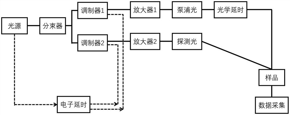
[0024] Such as figure 1 As shown, the multi-scale time-resolved spectrometer disclosed in this embodiment includes one pump light and one probe light, and the spectrometer includes a light source module, a beam splitter, a modulator 1, a modulator 2, an amplifier 1, an amplifier 2, and a pump light generator Module, probe light generation module, time delay module, sample chamber and data acquisition module, the light source module generates laser light with a specified wavelength, which can be a femtosecond laser system or a picosecond laser system, including an oscillator and an amplifier; the beam splitter is set on the light source Afterwards, the laser beam output by the light source is divided into two beams, and a fiber beam splitter, a beam splitter or other beam splitting optical components can be used; the modulator 1 and the modulator 2 are respectively arranged on the two beam-splitting paths , controlling the light at different times is also called the seed light ...
Embodiment 2
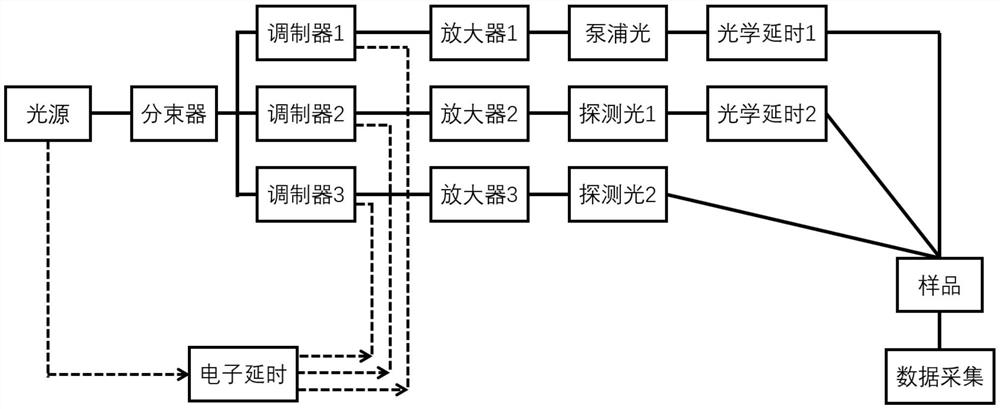
[0026] Such as figure 2 As shown, the multi-scale time-resolved spectrometer disclosed in this embodiment has 2 detection light modules and 2 optical delay modules. The detection light is composed of detection light 1 and detection light 2. 1 may be a narrow-linewidth laser generating module, and the probe light 2 is arranged behind the amplifier 3 for generating narrow-pulse laser light.
[0027] The delay module includes an optical delay module and an electronic delay module. The optical delay module includes two optical delay modules: the first optical delay module 1 is set at any position between the modulator and the sample in the pump light path , by changing the optical path difference between the pump light and the two probe lights, the delay is generated and controlled, generally from tens of attoseconds to tens of nanoseconds; the second optical delay module 2 is set at the detection At any position between the modulator and the sample in any optical path of the li...
Embodiment 3
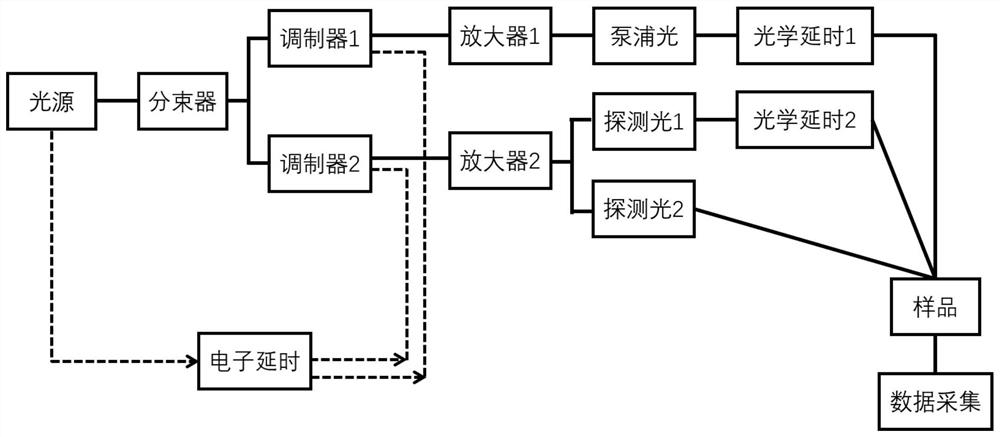
[0029] Such as image 3 As shown, the difference between the multi-scale time-resolved spectrometer disclosed in this embodiment and Embodiment 2 is that the two detection lights are composed of one amplifier module, the detection light 1 module and the detection light 2 module, which can save a modulator and amplifier, and the optical path more concise.
PUM
 Abstract
Description
Claims
Application Information