Non-contact conductivity measurement device and method based on LC circuit

A conductivity measurement, non-contact technology, applied in the direction of fluid resistance measurement, etc., can solve the problems that the conductive solution can no longer be equivalent to a resistance, the bandwidth is required, and the measurement model is complicated, so as to facilitate the design, reduce the bandwidth requirement, The effect of reducing requirements

Active Publication Date: 2020-10-09
ZHEJIANG UNIV
View PDF5 Cites 5 Cited by
  • Summary
  • Abstract
  • Description
  • Claims
  • Application Information

AI Technical Summary

Problems solved by technology

The first defect is that the high-frequency method increases the requirements for subsequent detection circuit components, such as the requirements for the bandwidth of the operational amplifier; the second defect is that strictly speaking, the use of the high-frequency method will make the gap between the two electrodes Conductive solution can no longer be equivalent to a resistor
Studies have shown that when the excitation frequency is higher than 1MHz, the capacitive component of the conductive solution itself cannot be ignored. At this time, the conductive solution between the two electrodes can no longer be equivalent to a resistance, and the corresponding measurement model will become very complicated.

Method used


Image

  • Non-contact conductivity measurement device and method based on LC circuit
  • Non-contact conductivity measurement device and method based on LC circuit
  • Non-contact conductivity measurement device and method based on LC circuit

Examples


Embodiment Construction

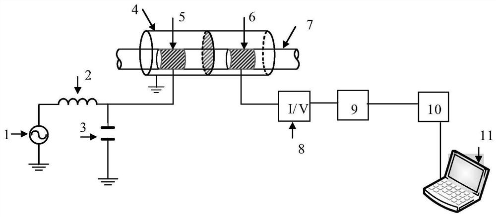
[0023] Such as figure 1 As shown, a non-contact conductivity measurement device based on LC circuit, including AC excitation source 1, inductance module 2, capacitor 3, metal shield 4, excitation electrode 5, detection electrode 6, insulating pipe 7, current-to-voltage module 8. Signal processing module 9, data acquisition module 10, computer 11; excitation electrode 5 and detection electrode 6 are arranged on the outer wall of insulating pipe 7; metal shield 4 is arranged on the periphery of excitation electrode 5 and detection electrode 6 for shielding electromagnetic influence ; The AC excitation source 1 is connected to one end of the inductance module 2, the other end of the inductance module 2 is connected to the excitation electrode 5, and is also connected to one end of the capacitor 3, and the other end of the capacitor 3 is connected to the ground; the detection electrode 6 is connected to the current switch The input ends of the voltage module 8 are connected, and t...


PUM

PropertyMeasurementUnit
lengthaaaaaaaaaa

Abstract

The invention discloses a non-contact conductivity measurement device and method based on an LC circuit. The device comprises an alternating current excitation source, the LC circuit, an annular two-electrode sensor, a current-to-voltage conversion module, a signal processing module, a data acquisition module and a microcomputer. The annular two-electrode sensor is composed of a metal shielding case, an excitation electrode, a detection electrode and an insulating pipeline, and non-contact measurement can be realized. The metal shielding cover is arranged around the sensor and used for shielding external electromagnetic interference. The alternating-current excitation source provides sinusoidal excitation signals, the LC circuit comprises an inductance module and a capacitor, two ends of an actual inductor in the inductance module are respectively connected with the alternating-current excitation source and the excitation electrode, and the detection electrode is connected with the current-to-voltage conversion module. According to the invention, the values of the inductance L and the capacitance C of the LC circuit are reasonably selected so that the whole measuring circuit worksin a low-frequency state, i.e., a larger fluid conductivity measuring range and sensitivity can be obtained at a lower working frequency, and beneficial reference is provided for measuring the conductivity of the conductive fluid in the pipeline at the lower working frequency.

Description

technical field [0001] The invention relates to fluid conductance detection technology, in particular to a non-contact conductance measurement device and method based on LC circuits. Background technique [0002] Fluids in pipelines widely exist in industrial processes such as metallurgy, chemical engineering, biomedicine, environmental protection and governance. Conductance is one of the most basic physical parameters of fluids, and its changes reflect the differences in many physical and chemical properties of fluids. Therefore, the online detection of conductance plays an important role in the analysis and measurement of other fluid characteristic parameters such as concentration, composition, chemical reaction rate, etc., and the research on related measurement devices and methods also has important scientific significance and industrial application value. [0003] Capacitive coupling non-contact conductivity detection technology (C 4 D) is a new type of non-contact co...

Claims


Application Information

Patent Timeline
Patent Type & Authority Applications(China)
IPC IPC(8): G01R27/22
CPCG01R27/22
Inventor 黄志尧黄强何宇晨郭紫薇冀海峰王保良
Owner ZHEJIANG UNIV
Why Eureka
Try Eureka