Magnetic suspension flywheel energy storage motor generator
A flywheel energy storage and generator technology, applied in the direction of controlling generators, machines/engines, battery circuit devices, etc., can solve problems such as difficult heat dissipation of the system
- Summary
- Abstract
- Description
- Claims
- Application Information
AI Technical Summary
Problems solved by technology
Method used
Image

Examples
Embodiment 1
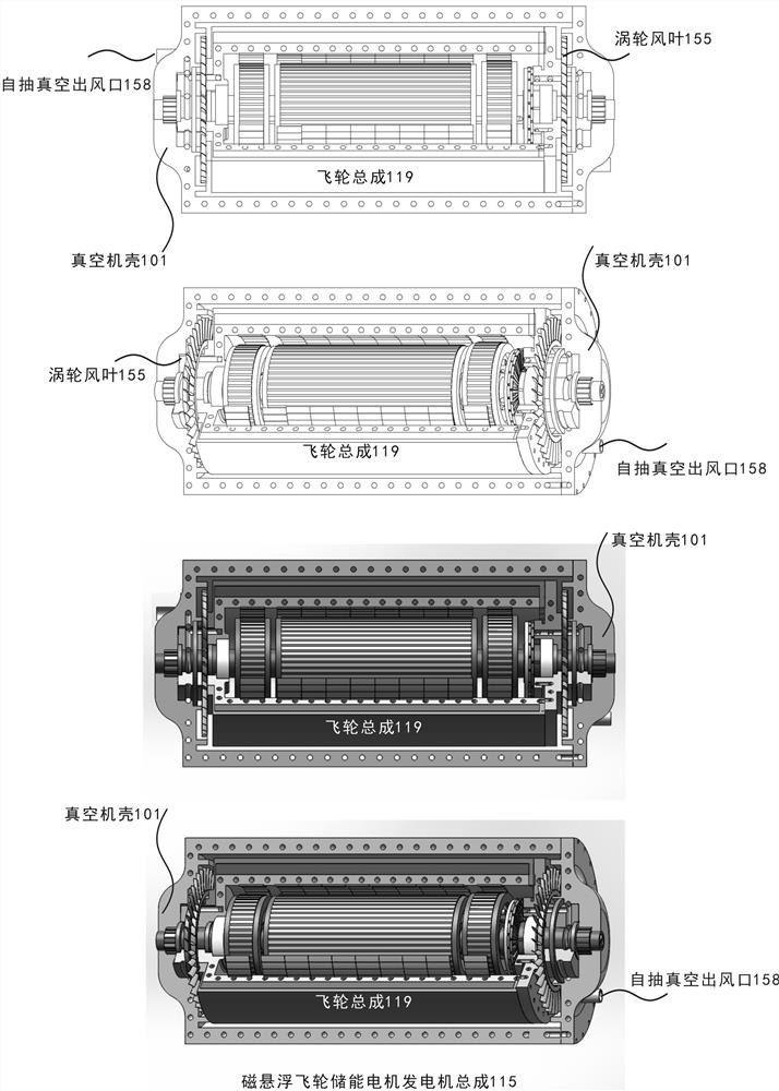
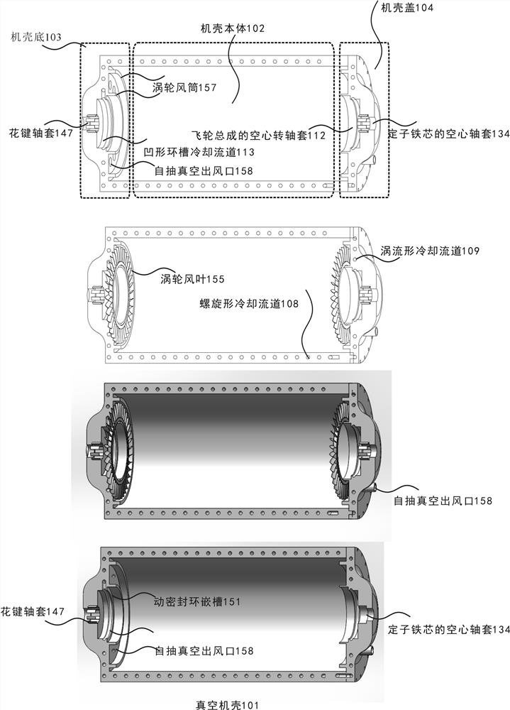
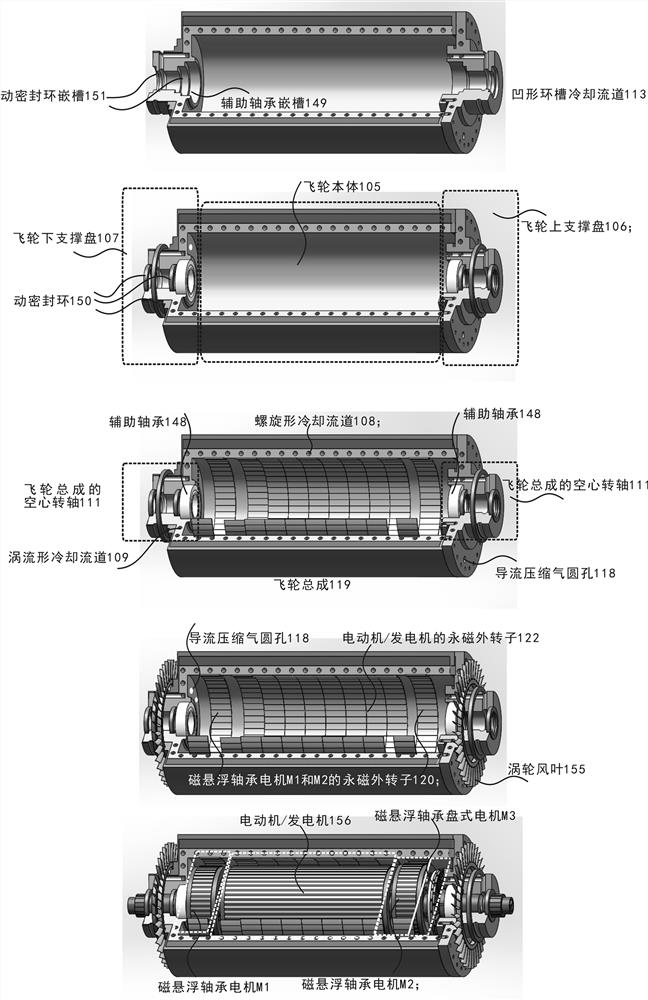
[0077] Example 1: See Figure (1-4).
[0078] Step 1. A specific assembly step, the overall assembly of the magnetic levitation flywheel energy storage motor generator assembly 115 .
[0079] Step 2. The stator core winding 125 of the motor / generator is assembled with the hollow shaft 133 of the stator core: the inner circular convex keyway of the stator core winding 125 of the motor / generator is aligned with the outer circle of the hollow shaft 133 of the stator core Recessed keyway, press in and lock.
[0080]Step 3. Assemble the two stator core windings 123 of the magnetic suspension bearing motor with the hollow shaft 133 of the stator core: the inner circular convex key grooves of the two stator core windings 123 of the magnetic suspension bearing motor are aligned with the outer circle of the hollow shaft 133 of the stator core The concave keyway is press-fitted and locked, and is placed on the stator core winding 125 of the motor / generator symmetrically.
[0081] Step ...
Embodiment 2
[0091] Example 2: Please refer to Figure (5-6).
[0092] The power controller system of the magnetic levitation flywheel energy storage motor generator assembly has four working modes: energy storage charging mode, energy maintaining operation mode, energy releasing and discharging mode and shutdown mode.
[0093] The ECU control uses a 64-bit computer to receive voltage, current, pressure, Temperature, rotational speed, and rotation angle sensor information; according to this information, the calculated results are transformed and output as control signals, and the comparison and calculated results are used to control the magnetic suspension magnetic force of the magnetic bearing motor and the magnetic bearing disc motor, and the motor / generator required Control of torque, power, pressure and temperature.
[0094] The control core component of the magnetic suspension bearing motor M1, M2, M3 magnetic suspension bearing system is the external power supply HVECU or Sc super ca...
Embodiment 3
[0097] In another embodiment 3: flywheel energy storage and supercapacitor energy storage hybrid electric bus.
[0098] It is mainly composed of three parts: the bus hub drive motor module, the super capacitor energy storage module and the flywheel energy storage module. The hub drive motor is 100 kW, the second set of super capacitor energy storage modules is 16 kWh, and the magnetic levitation flywheel energy storage motor generator set has 96kWh energy storage , each maglev flywheel energy storage motor generator 2kWh is 180mm long, 230 mm in diameter, 23kg in mass, and rotates at 200,000 r / min. A total of 48 maglev flywheel energy storage motor generators weigh 1052 kg in total, and the total energy storage of the flywheel group is 96kWh, placed in the chassis of the bus, can enable the 16-ton flywheel energy storage and supercapacitor energy storage hybrid bus to travel 250 km at a speed of 1000km / h, without the need to set up charging piles at each bus station. It is ben...
PUM
 Abstract
Description
Claims
Application Information
 - R&D
- Intellectual Property
- Life Sciences
- Materials
- Tech Scout
- Unparalleled Data Quality
- Higher Quality Content
- 60% Fewer Hallucinations
Browse by: Latest US Patents, China's latest patents, Technical Efficacy Thesaurus, Application Domain, Technology Topic, Popular Technical Reports.
© 2025 PatSnap. All rights reserved.Legal|Privacy policy|Modern Slavery Act Transparency Statement|Sitemap|About US| Contact US: help@patsnap.com