A method and device for slowing down the corrosion of the condensate stripping tower top reflux system

A technology of condensate and stripper, which is applied in the fields of coal chemical industry and petroleum processing, can solve the problems of restricting the long-term stable operation of the device, corrosion and leakage of the tower top condenser, and threats to the safety production of the device, so as to reduce maintenance costs and ensure safety. , the effect of large spray area

Active Publication Date: 2021-12-17
CHINA PETROLEUM & CHEM CORP +1
View PDF14 Cites 0 Cited by
  • Summary
  • Abstract
  • Description
  • Claims
  • Application Information

AI Technical Summary

Problems solved by technology

[0004] However, there is a common problem of corrosion leakage in the overhead condenser designed with a reflux system
Most of the factories with corrosion occur between half a year and one year after driving. The corroded materials are all stainless steel, which seriously restricts the long-term stable operation of the device. While posing a great threat to the safe production of the device, it also brings certain risks. economic loss and environmental damage

Method used


Image

  • A method and device for slowing down the corrosion of the condensate stripping tower top reflux system

Examples


Embodiment 1

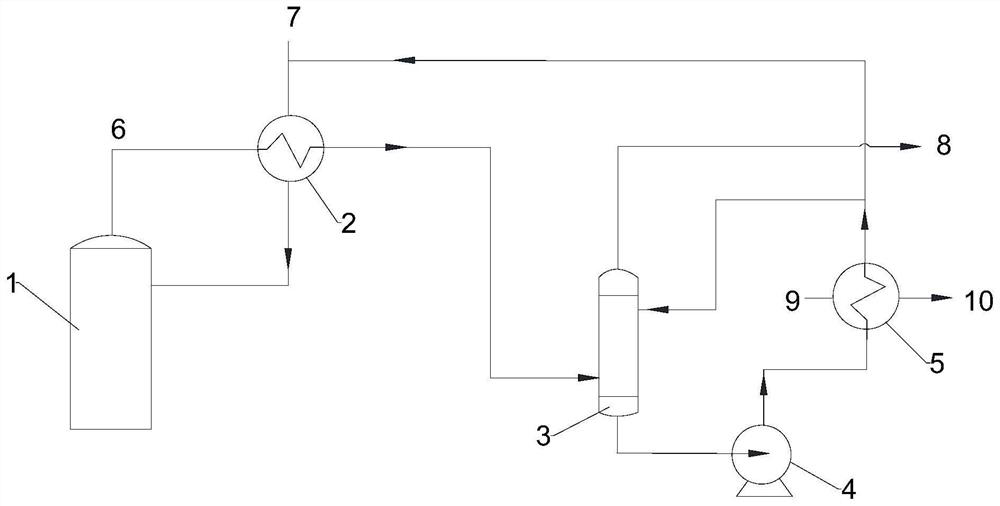
[0063] Please refer to figure 1 , the present embodiment provides a device for slowing down the corrosion of the condensate stripper overhead reflux system, which includes a condensate stripper 1 (single tower), a feed heat exchanger 2, a spray tower 3, a reflux pump 4 and Reflux heat exchanger 5, the inlet of feed heat exchanger 2 communicates with the tower top outlet of condensate stripping tower 1, the inlet of the tower bottom of spray tower 3 communicates with the outlet of feed heat exchanger 2, and reflux pump 4 The inlet of the pump is connected with the outlet at the bottom of the spray tower 3, the outlet of the reflux pump 4 is connected with the inlet of the reflux heat exchanger 5, and the outlet of the reflux heat exchanger 5 is respectively connected with the inlet of the top of the spray tower 3 and the condensed liquid vapor The entrance on the top of the tower 1 is connected. The recuperator 5 is also provided with a circulating cooling water inlet 9 and a ...

Embodiment 2

[0068] This embodiment provides a device for slowing down the corrosion of the condensate stripping tower overhead reflux system, which includes a condensate stripping tower (double tower), a feed heat exchanger, a spray tower, a reflux pump and a reflux heat exchanger, The inlet of the feed heat exchanger is connected with the top outlet of the condensate stripping tower, the inlet of the bottom of the spray tower is connected with the outlet of the feed heat exchanger, and the inlet of the reflux pump is connected with the outlet of the bottom of the spray tower The outlet of the reflux pump communicates with the inlet of the reflux heat exchanger, and the outlet of the reflux heat exchanger communicates with the inlet at the top of the spray tower and the inlet at the top of the condensate stripping tower respectively. The return heat exchanger is also provided with a circulating cooling water inlet and a circulating cooling water outlet.

[0069] Using the above-mentioned ...


PUM


Abstract

The application provides a method and device for slowing down the corrosion of the top reflux system of a condensate stripper, which relates to the technical fields of coal chemical industry and petroleum processing. The device includes a condensate stripping tower and a spray tower, and the non-condensable gas output from the top of the condensate stripping tower is cooled by using the spray tower. The above-mentioned device is simple in structure and easy to operate. Using the spray tower as the non-condensable gas cooling system to replace the traditional tower top condenser can effectively solve or slow down the local serious ammonia substances in the tower top reflux system in the existing condensate stripping process. Corrosion Corrosion problems, reduce inspection and maintenance costs Avoid or reduce unplanned shutdowns caused by leakage problems, reduce maintenance costs, and ensure the safe, stable, and long-term operation of the entire stripping system.

Description

technical field [0001] The invention relates to the technical fields of coal chemical industry and petroleum processing, in particular to a method and a device for slowing down the corrosion of the top reflux system of a condensate stripping tower. Background technique [0002] The CO conversion process is a key link in the coal chemical production process and an important purification process in the synthesis of ammonia, methanol and hydrogen production. In order to meet the requirements of water saving and energy saving, the process condensate of coal gasification coal water slurry process and dry powder process will be recycled. [0003] The function of the condensate stripping tower in the conversion section is to strip the ammonia in the low-temperature condensate returned to the gasification to maintain the ammonia balance in the system. The stripping effect will directly affect the ammonia index in the gasification ash water, thereby affecting to the discharge of gas...

Claims


Application Information

Patent Timeline
Patent Type & Authority Patents(China)
IPC IPC(8): B01D5/00B01D3/38
CPCB01D5/0093B01D5/003B01D3/38
Inventor 刘希武曹振兴崔新安陈章淼刘旭霞李辉邹洋高阳赵小燕
Owner CHINA PETROLEUM & CHEM CORP
Why Eureka
Try Eureka