Rapid-punching punching machine

A punching and fast technology, applied in the field of presses, can solve the problems of high energy consumption, residual products, scrapped products, etc., and achieve the effect of solving the accumulation of impurities, simplifying the subsequent processes, and reducing the manufacturing cost

Inactive Publication Date: 2020-10-13
应开法
View PDF0 Cites 1 Cited by
  • Summary
  • Abstract
  • Description
  • Claims
  • Application Information

AI Technical Summary

Problems solved by technology

However, this method is limited by the flow characteristics of powder raw materials, and often cannot fill the mold quickly, especially for molds with large cavity depth and large size, which limits the filling capacity of the feeding trolley. The speed also affects the overall processing efficiency of the workpiece
And if the powder raw material fails to fill or meet the filling compactness standard, it will also lead to the appearance of residual products and scrapped products.
[0004] 2. When the workpiece is conveyed along the workbench after forming, it is inevitable that some powder raw materials will remain on the surface. This part of impurities will affect the subsequent washing, sintering and other processes, and it needs to be removed. The traditional method Use high-pressure gas flushing, water washing, etc. to remove this part of the impurities, but these methods either consume high energy or waste resources seriously
For small batches and various types of workpieces, multiple batching methods are required, and the batching methods are frequently switched. If the method of prefabricating raw materials in advance is used to cooperate with production, it is obviously not conducive to the short, flat, fast, and flexible production characteristics of powder metallurgy.

Method used


Image

  • Rapid-punching punching machine
  • Rapid-punching punching machine
  • Rapid-punching punching machine

Examples


Embodiment Construction

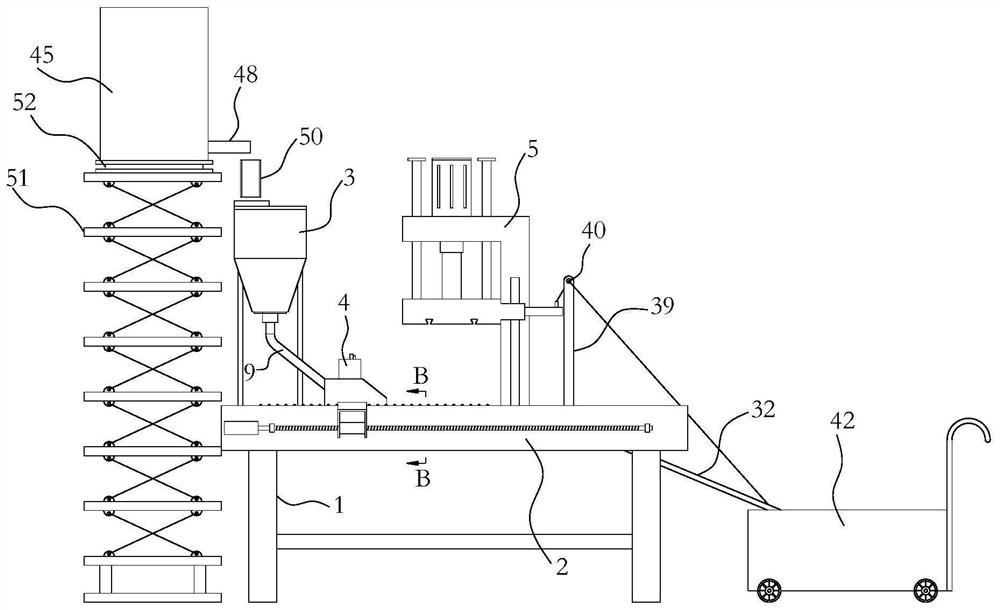
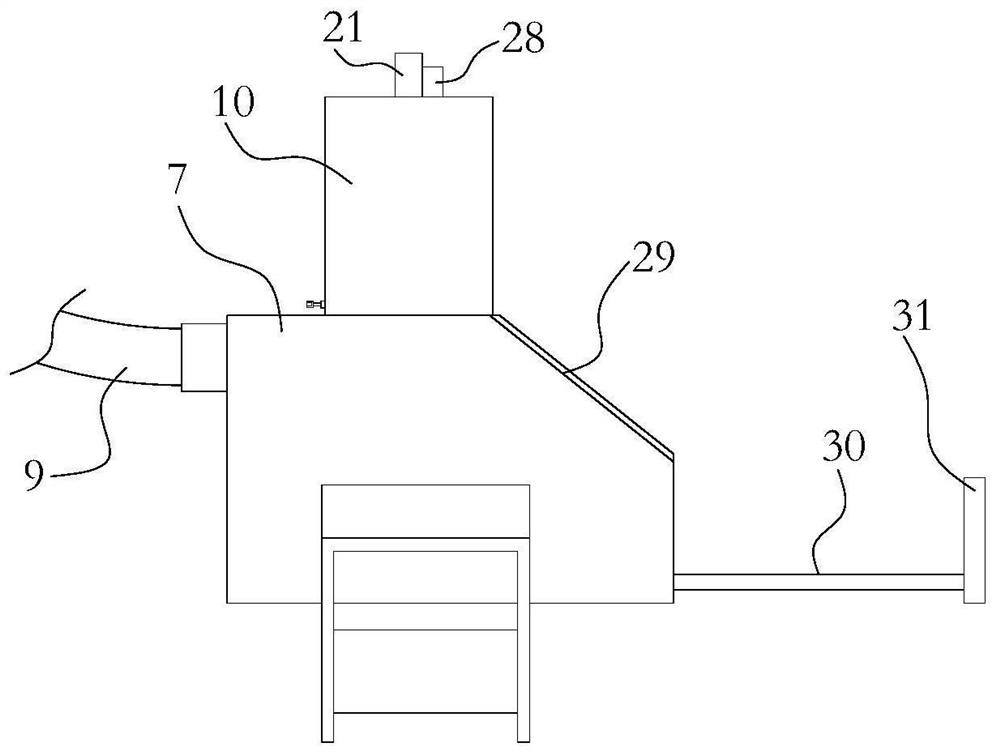
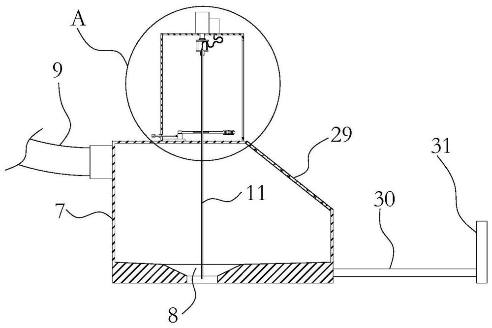
[0033] Such as Figure 1-13 As shown, a punching machine is used for powder metallurgy, which directly compresses powder raw materials. The basic structure of the present invention is the same as that of a traditional powder metallurgy punching machine, including a frame 1 and a raw material storage mixing cylinder 3, a filling trolley 4, and a stamping forming device 5 arranged sequentially on the working table 2 of the frame 1, and the stamping forming device 5 A molding die 6 is arranged below. The frame 1 is used as an installation basis, and the workbench 2 on it is used for the installation of various devices of the present invention; the raw material storage mixing cylinder 3 is used for storing powdery raw materials, and for stirring and mixing the powdered raw materials. A stirring mechanism is arranged inside to ensure the uniformity of raw material mixing in the raw material storage mixing cylinder 3 . The filling trolley 4 is used to walk on the workbench 2 and c...


PUM


Abstract

The invention relates to the technical field of press machines and provides a rapid-punching punching machine which is capable of effectively removing extra impurities on a workpiece. The punching machine comprises a rack, a raw material storage mixing cylinder, a material filling trolley and a punching forming device; the raw material storage mixing cylinder, the material filling trolley and thepunching forming device are arranged on a workbench of the rack in sequence; a forming mold is arranged below the punching forming device; a downwardly inclined material unloading plate is arranged onthe workbench on the side where the forming mold is away from the raw material storage mixing cylinder; the material unloading plate is composed of a plate body and a rubber cushion which is arrangedon the upper surface of the plate body; a plurality of flanges are arranged in parallel on the rubber cushion and extend towards the width direction of the material unloading plate; the sections of the flanges are in semicircular shapes; and a plurality of slag leakage holes are evenly formed in the material unloading plate and penetrate through the rubber cushion and the plate body. The punchingmachine can rapidly remove powder impurities adhered to the surface of a formed workpiece, the structure is simple, the manufacturing cost is low, promotion is convenient, and following working procedures are simplified.

Description

technical field [0001] The invention relates to the technical field of presses, in particular to a rapid stamping press. Background technique [0002] The press is a comprehensive equipment that generates the motive force through hydraulic cylinders, motors, cylinders, etc., and applies force to the workpiece through a series of complex mechanical transmissions, and is used for shearing, compacting, punching, etc. of the workpiece. Powder metallurgy is a new type of powder metallurgy that mixes metal powder with metal powder, or metal powder with non-metallic powder, and then uses a punch press to directly press the metal powder into a workpiece of a specific shape, or press it into a specific shape and then sinter it. The production process, which has many advantages such as less material waste and high production flexibility, is currently widely used in various industries. It usually includes a workbench and a feeding trolley, punch, mold, etc. set on it. When in use, the...

Claims


Application Information

Patent Timeline
Patent Type & Authority Applications(China)
IPC IPC(8): B22F3/03
CPCB22F3/03
Inventor 应开法
Owner 应开法
Why Eureka
Try Eureka