Fluorescence immunoassay analyzer

A fluorescence immunoassay, optical structure technology, applied in the analysis of materials, fluorescence/phosphorescence, material analysis by optical means, etc., can solve the problems of limited application scenarios, high risk of biological contamination, waste of time and use costs, etc. The effect of saving operation time, ensuring detection throughput, and shortening detection time

Pending Publication Date: 2020-10-16
ZYBIO INC
View PDF0 Cites 8 Cited by
  • Summary
  • Abstract
  • Description
  • Claims
  • Application Information

AI Technical Summary

Problems solved by technology

[0005] Existing fully automatic instruments, which can complete automatic card feeding and automatic sample feeding, all need to be equipped with a complex automatic sample feeding system, which has a high failure rate, high risk of biological contamination, and cumbersome pre-treatment of the static samples to be tested. It is difficult to detect whole blood samples and peripheral whole blood samples, and the instrument is bulky and its application scenarios are limited. It can only be used in laboratory departments of medium and large hospitals. However, compared with fully automatic luminescent and biochemical instruments in this scenario, the detection speed and Accuracy does not have an advantage
In addition, many instruments on the market need to use the ID card or IFID card to pre-enter the reagent calibration information and update the database before testing a new batch of reagent items before testing. If the operator accidentally loses the ID card or forgets to insert it before use card, it will cause waste of time and cost

Method used


Image

  • Fluorescence immunoassay analyzer
  • Fluorescence immunoassay analyzer
  • Fluorescence immunoassay analyzer

Examples


Embodiment 1

[0067] The invention provides a fluorescence immunoassay analyzer.

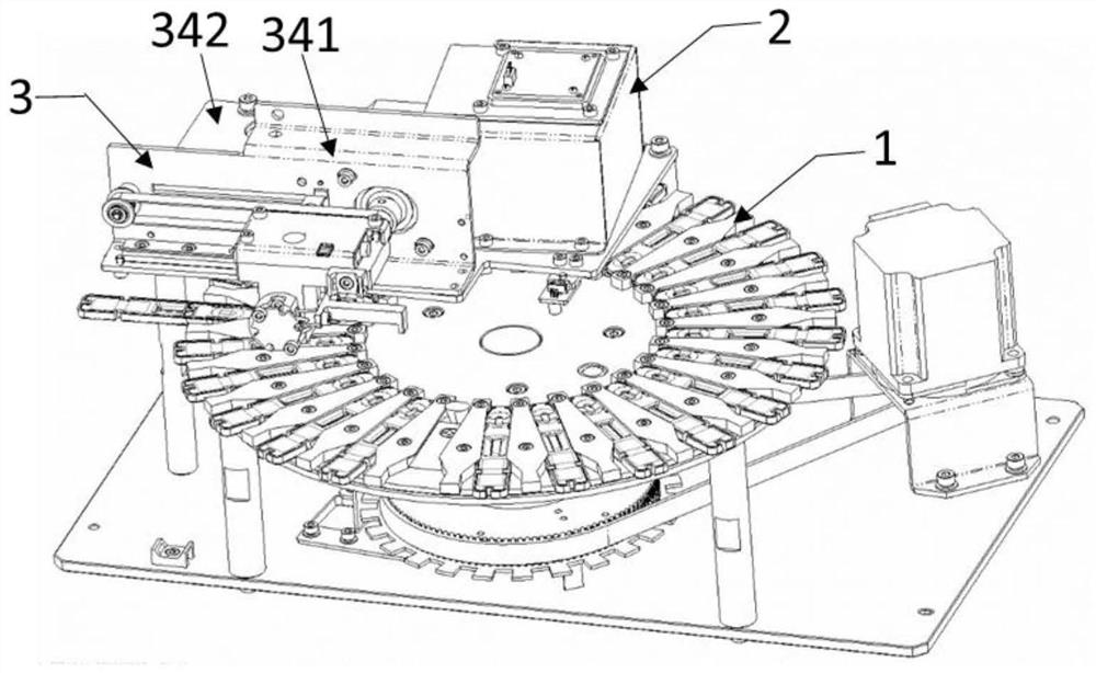
[0068] A fluorescent immunoassay analyzer, such as figure 1 with Figure 5 As shown, it includes an incubating tray mechanism 1, a photo identification mechanism 2, a card scanning and kicking mechanism 3, and a door closing mechanism 4.

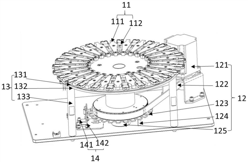
[0069] Such as figure 2 As shown, the incubating plate mechanism 1 includes a turntable 11 , a driving structure 12 and a constant temperature heating structure 13 , the driving structure 12 is connected to the axis of the turntable 11 , and the drive structure 12 drives the turntable 11 to rotate. The constant temperature heating structure 13 is installed under the turntable 11 .

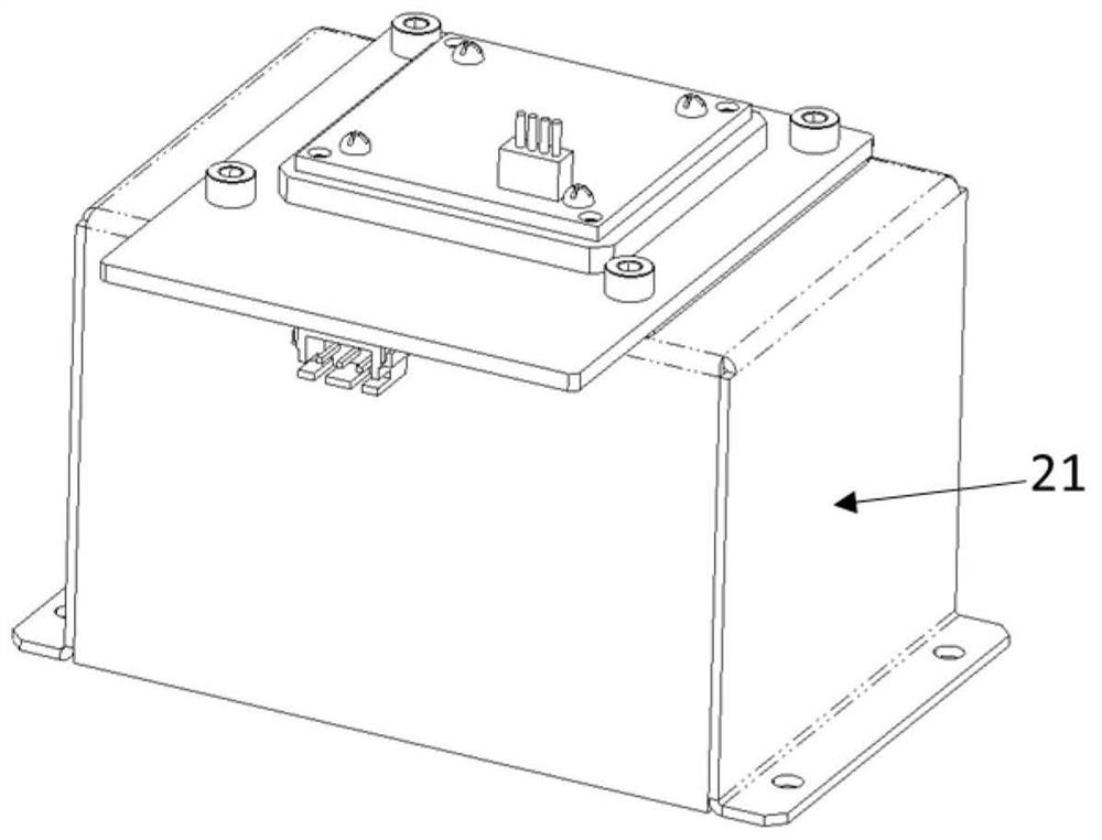
[0070] Such as image 3 As shown, the photographing identification mechanism 2 includes a dark box structure 21 and a photographing structure (not shown in the figure), the photographing structure is located in the dark box and faces the incubation plate, and the photographing identificatio...

Embodiment 2

[0102] The difference between this embodiment and Embodiment 1 lies in the installation hole, the spring, the steel ball at the upper end of the spring and the cover plate installed on the reaction disk are installed in the installation hole, the cover plate covers part of the steel ball, and the steel ball The shape matches the bottom shape of the reagent card.

Embodiment 3

[0104] The difference between this embodiment and Embodiment 1 is that there are two photoelectric switches 322, both of which are arranged on the mounting board, and the two photoelectric switches correspond to the second reset flap, and the second reset flap It is arranged on the slider, wherein the photoelectric switch is arranged at the initial position of the optical mechanism 32 (that is, the zero position close to the inner side of the turntable 11), and the second reset shutter is used together to determine whether the optical structure 32 is at the initial position. The other photoelectric switch is arranged at the position when the optical structure 32 completes the card kicking action, and is used in conjunction with the second reset shutter to determine whether the optical structure 32 has correctly completed the card kicking action.


PUM


Abstract

The invention relates to the technical field of detection, and discloses a fluorescence immunoassay analyzer, which comprises an incubation disc structure, and a photographing recognition mechanism and a scanning kicking mechanism which are positioned above the incubation disc. Rapid and high-throughput detection is realized by using a compact and simple instrument structure, the analyzer is suitable for various detection scenes, and has extremely high application value.

Description

technical field [0001] The invention relates to the technical field of detection, in particular to a fluorescent immunoassay analyzer. Background technique [0002] The main function of the fluorescent immunoassay analyzer is: in vitro quantitative detection of the content of various proteins, antigens and other items in human serum, plasma, whole blood or urine, for the diagnosis, prevention, treatment and health monitoring of clinical diseases Provide true and accurate data basis. [0003] At present, most fluorescent immunoassay analyzers on the market are divided into several categories: one is single-channel instruments, which are relatively small in size and flexible in application scenarios, but can only test one sample at a time, with low test throughput and lack of Kicking the card and the device specially accommodating waste cards are easy to cause pollution. The other is a semi-automatic multi-channel instrument, which can complete incubation tests of multiple s...

Claims


Application Information

Patent Timeline
Patent Type & Authority Applications(China)
IPC IPC(8): G01N33/53G01N21/64G01N35/00
CPCG01N21/6428G01N33/5302G01N35/00029G01N2035/00148G01N2035/00376
Inventor 霍威王旭吴玲海张炜伍晋杰吴健吴佳龙
Owner ZYBIO INC
Why Eureka
Try Eureka