

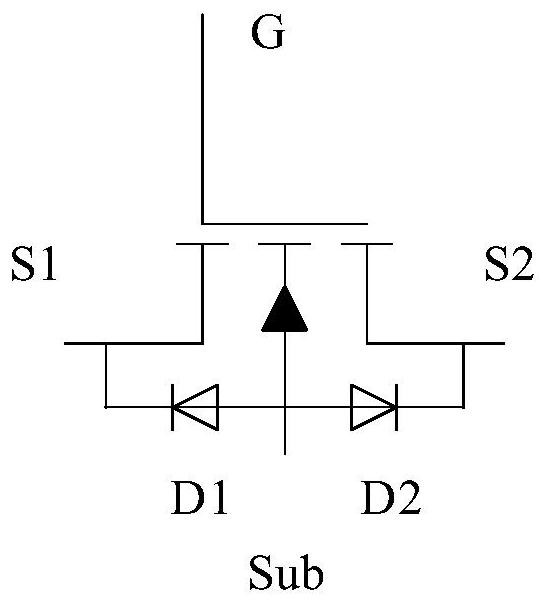
Bidirectional power device
A bidirectional power device, semiconductor technology, applied in semiconductor devices, electrical components, circuits, etc., can solve problems such as increased on-resistance and increased power consumption
- Summary
- Abstract
- Description
- Claims
- Application Information
AI Technical Summary
Problems solved by technology
Method used
Image

Examples
no. 1 example
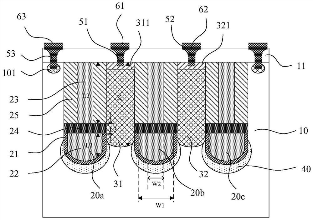
[0077] Figure 2-Figure 4 A cross-sectional view and a top view of the bidirectional power device according to the first embodiment of the present invention are respectively shown; wherein, figure 2 for Figure 4 Sectional view taken along line AA' in the top view shown, image 3 for Figure 4 Sectional view taken along line BB' in top view shown. In this embodiment, the bidirectional power device is a trench device, which may be a metal oxide semiconductor field effect transistor (MOSFET), an IGBT device or a diode. In the following, an N-type MOSFET is taken as an example for illustration, however, the present invention is not limited thereto.
[0078] exist figure 2 The bidirectional power device shown in only contains a schematic diagram of the longitudinal structure of a cell structure, but in actual products, the number of cell structures can be one or more. see Figure 2-Figure 4 , the bidirectional power device includes a semiconductor layer 10, a trench 20 lo...
no. 2 example
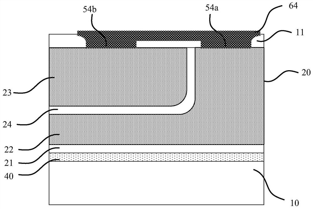
[0102] This embodiment adopts basically the same technical solution as the first embodiment, the difference is that in the first embodiment, the control grid 22 and the shielding grid 23 are connected together, while in this embodiment, the shielding grid 23 and the semiconductor layer 10 connected together, such as Image 6 As shown, the contact hole 54b of the shielding grid 23 is connected to the contact hole 53 of the substrate electrode, so that the shielding grid 23 and the substrate electrode Sub are electrically connected together.
[0103] In this embodiment, the remaining parts of the bidirectional power device are basically the same as those in the first embodiment, and the specific structure will not be repeated here.
[0104] In the first embodiment, the control gate 22 and the shielding gate 23 are connected together, the shielding gate 23 overlaps with the source region 31 and the drain region 32 , and parasitic capacitance exists. When the voltage of the contr...
no. 3 example
[0107] This embodiment adopts basically the same technical solution as the first embodiment, the difference is that in the first embodiment, the third contact 63 is formed on the first surface of the semiconductor layer 10, through the third contact hole 53, the third The lead region 101 is in contact with the semiconductor layer 10 to form a substrate electrode Sub. However, in this embodiment, the third contact 63 is formed on the second surface of the semiconductor layer 10, such as Figure 7 shown. Specifically, a bidirectional power device is formed on a substrate 1 with a higher doping concentration, and then a metal layer is evaporated on the backside of the substrate 1 to form a third contact 63 .
[0108] In the first embodiment, the gate, the substrate electrode, the first output electrode and the second output electrode of the bidirectional power device are drawn from the first surface of the semiconductor layer 10, which is suitable for chip scale packaging (CSP)....
PUM
| Property | Measurement | Unit |
|---|---|---|
| Thickness | aaaaa | aaaaa |
| Doping concentration | aaaaa | aaaaa |
| Thickness | aaaaa | aaaaa |
Abstract
Description
Claims
Application Information