
Fluff fiber treatment method for pneumatic desorption type textile wastewater

A technology for textile wastewater and fiber treatment, which is applied in textile industrial wastewater treatment, adsorption water/sewage treatment, water treatment parameter control, etc. The problem of high concentration of pollutants

Inactive Publication Date: 2020-10-20
罗培佳
View PDF0 Cites 3 Cited by
  • Summary
  • Abstract
  • Description
  • Claims
  • Application Information

AI Technical Summary

Problems solved by technology

[0003] The textile wastewater mainly has the following characteristics: the treatment pool (1) has a large amount of water; the pollution of the wastewater is mainly organic pollution; the central winding rod (2) has a high concentration of pollutants; the pollutants in the wastewater are mainly the second type of harmful substances; (3 ) is mostly alkaline and has a high chroma; the water quality of the extended side-wound rod (4) changes greatly, and it is difficult for general wastewater treatment facilities to meet higher discharge standards
[0004] Because textile wastewater is mostly sewage from washing and dyeing of fabrics and threads, the interior contains more fluff fiber impurities. Due to its slender characteristics, when treating textile wastewater, although the interception of fluff fibers is relatively simple , but after it is intercepted, it is more complicated to be entangled on the intercepted object, which makes it very difficult for the staff to clean up the entangled wool fiber, and the desorption efficiency is low, which affects the overall efficiency of wastewater treatment.

Method used

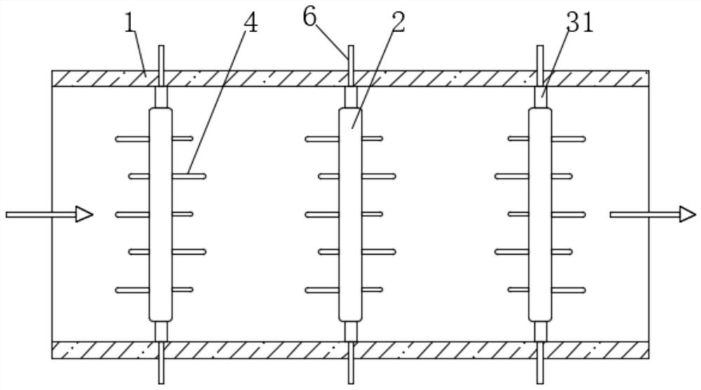
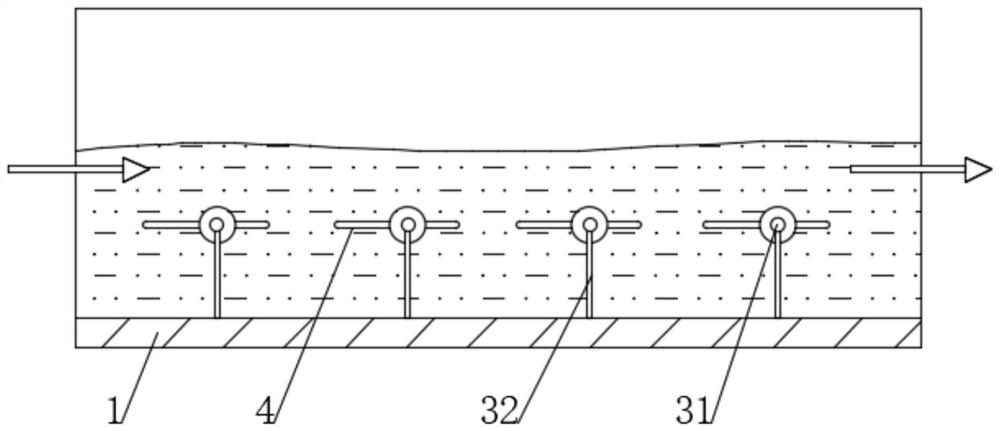

Image

  • Fluff fiber treatment method for pneumatic desorption type textile wastewater
  • Fluff fiber treatment method for pneumatic desorption type textile wastewater
  • Fluff fiber treatment method for pneumatic desorption type textile wastewater

Examples


Embodiment 1

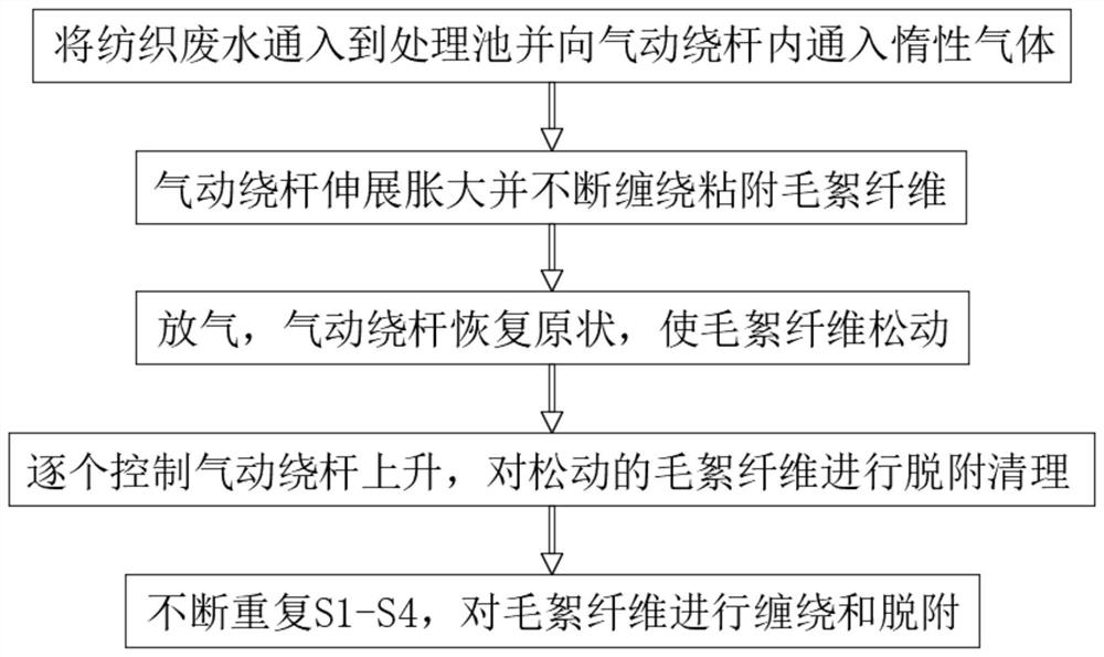
[0045] See figure 1 , A method for treating fluff fibers of pneumatic desorption textile wastewater, including the following steps:

[0046] S1. First, pass the textile wastewater into the treatment tank 1, and at the same time pass inert gas into the pneumatic winding rod in the treatment tank 1;

[0047] S2. After the inside of the pneumatic winding rod is inflated, it gradually expands and swells. The textile waste water continuously passes through the pneumatic winding rod, and the wool fibers in the textile waste water are continuously wound and adhered by the stretched and expanded pneumatic winding rod;

[0048] S3. When the woolen fiber with a lot of adhesion is wound on the pneumatic winding rod, the inert gas is released to make the pneumatic winding rod return to its original state. At this time, the wool fiber on the pneumatic winding rod surface becomes loose and is connected with the pneumatic winding rod. There is a large gap between;

[0049] S4. At this time, the pneu...


PUM


Abstract

The invention discloses a fluff fiber treatment method for pneumatic desorption type textile wastewater, and belongs to the field of wastewater treatment. In the fluff fiber treatment method for pneumatic desorption type textile wastewater, pneumatic winding rods are arranged, firstly, the pneumatic winding rods are inflated so as to be stretched and expanded, and the rotation of the pneumatic winding rods is controlled to carry out winding adsorption of fluff fibers; and in desorption, the pneumatic winding rod is deflated, the gas support is lost inside, the central winding rod and the extension side winding rod are in a flat state, at the moment, wound batting fibers are not tightly wound with the central winding rod and the extension side winding rod, meanwhile, through cooperation with the effects of the surface layer winding sheet and the embedded winding layer, the winding adsorption effect of the surface of the pneumatic winding rods on fluff fibers can be effectively improvedunder the condition that fluff fiber desorption is not affected, and then the treatment efficiency of the method on textile wastewater is remarkably improved.

Description

Technical field [0001] The invention relates to the field of wastewater treatment, and more specifically, to a method for treating fluff fiber of pneumatic desorption textile wastewater. Background technique [0002] Textile effluent is a variety of waste water generated in the process of spinning and weaving. Textile industry wastewater can be mainly divided into several categories: printing and dyeing wastewater, chemical fiber textile wastewater, degumming and scouring wastewater, among which the serious pollution is mainly printing and dyeing wastewater and chemical fiber textile wastewater. The textile printing and dyeing industry is one of the industrial sectors that consume a lot of water and discharge more wastewater. According to statistics, my country's printing and dyeing enterprises discharge 3 million to 4 million tons of wastewater every day. Textile industry wastewater generally contains suspended solids, grease, fiber scraps, surfactants and various dyes. For e...

Claims


Application Information

Patent Timeline
IPC IPC(8): C02F1/28C02F103/30
CPCC02F1/28C02F2103/30C02F2209/10C02F2303/16
Inventor 罗培佳
Owner 罗培佳
Learn More