Gas turbine combustion state parameter monitoring system based on TDLAS technology

A combustion state and gas turbine technology, applied in gas turbine engine testing, jet engine testing, engine testing, etc., can solve the problems of complex composition of combustion state monitoring system and low measurement accuracy of state parameters

Pending Publication Date: 2020-10-20
XIAN THERMAL POWER RES INST CO LTD
View PDF10 Cites 12 Cited by
  • Summary
  • Abstract
  • Description
  • Claims
  • Application Information

AI Technical Summary

Problems solved by technology

[0006] In order to solve the problems of complex composition of the gas turbine combustion state monitoring system in service and low measurement accuracy of state parameters such as pressure pulsation and combustion temperature, the present invention provides a gas turbine combustion state parameter monitoring system based on TDLAS technology. The system is based on laser wavelength modulation absorption method, using the near-infrared laser output can be combustor gaseous H 2 O absorbs two single-mode lasers with different wavelengths, and makes the laser pass through the flow field of the combustion chamber, and then uses a photodetector to convert the laser spectral signal absorbed by the water vapor in the combustion chamber into an electrical signal, and analyzes the two different wavelengths The light intensity and signal width of the laser absorption line, the line function, the second harmonic peak and other information, ...

Method used


Image

  • Gas turbine combustion state parameter monitoring system based on TDLAS technology
  • Gas turbine combustion state parameter monitoring system based on TDLAS technology
  • Gas turbine combustion state parameter monitoring system based on TDLAS technology

Examples


Embodiment

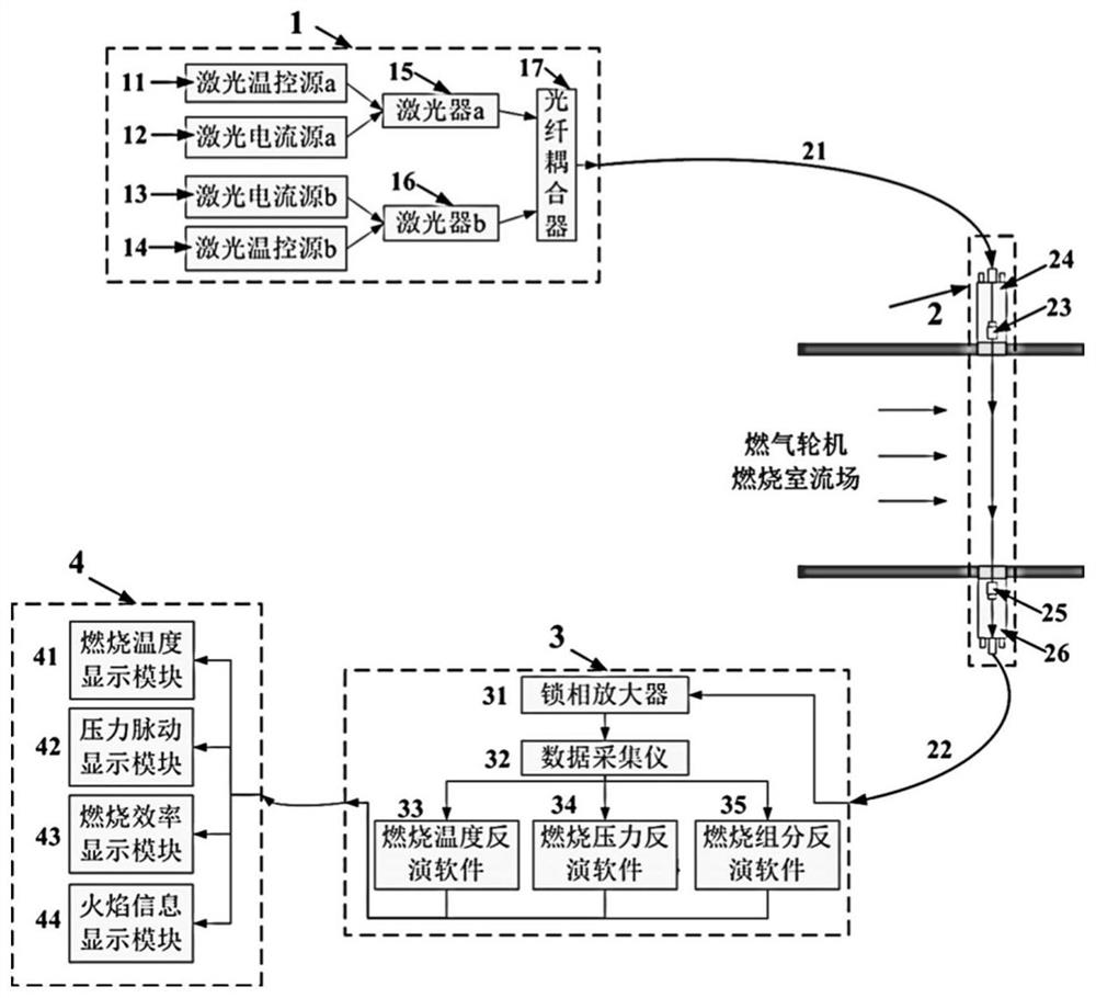
[0048] Such as Figure 4 As shown, when the combustion chamber of the gas turbine is working, the laser emission module 1 and the laser data analysis and processing module 3 are arranged at the far end of the gas turbine, and the laser collimator 23 and the collimator cooling sleeve 24 are installed at the upper end of the outlet of the combustion chamber of the gas turbine. The distance between the axis of the laser collimator 23 and the exit plane of the flame cylinder is 100mm, the photodetector 25 and the photodetector cooling sleeve 26 are installed at the lower end of the outlet of the transition section of the combustion chamber of the gas turbine, and the center of the detection window of the photodetector 25 is The distance from the exit plane of the transition section is also 100 mm, and the laser collimator 23 and the photodetector 25 are both perpendicular to the gas flow direction at the exit of the transition section of the combustion chamber of the gas turbine. ...


PUM


Abstract

The invention discloses a gas turbine combustion state parameter monitoring system based on a TDLAS technology. The gas turbine combustion state parameter monitoring system comprises a laser emissionmodule, a laser transmission module, a laser data analysis processing module and a combustion state display module which are sequentially connected. During working, required incident laser is generated through the laser emission module; the incident laser and the laser absorbed by the flow field of a combustion chamber are transmitted through a laser transmission module, and a laser signal is converted into an electric signal; effective electric signals are extracted through a laser data analyzing and processing module, flow field temperature, pressure and H2O concentration are inverted, pressure pulsation characteristics are analyzed, combustion efficiency is calculated, and whether flames exist or not is judged; the combustion flow field temperature, the pressure pulsation characteristics, the flame, the combustion efficiency and the like are displayed through a combustion state parameter display module. The combustion state parameters of the gas turbine are measured by adopting a non-contact method, the method has the advantages of no interference to the flow field, wide measurement range, high precision, quick response, simple system composition and the like, and the combustionstate monitoring system of the in-service gas turbine can be simplified.

Description

technical field [0001] The invention belongs to the technical field of gas turbines, in particular to a monitoring system for combustion state parameters of gas turbines based on TDLAS technology. Background technique [0002] The main task of gas turbine combustion diagnosis is to obtain state parameters such as combustion chamber pressure, temperature, and composition through effective methods, and then judge the combustion state of the combustion chamber, realize combustion stability, combustion temperature diagnosis, etc., and cooperate with the gas turbine control system to ensure that the combustion chamber Always operate in a safe, stable and low-emission state. [0003] The premise of combustion diagnosis is to realize the monitoring of combustion state. One is to monitor whether there is a flame in the combustion chamber, and the other is to monitor whether the outlet temperature of the combustion chamber meets the requirements and whether the combustion of the comb...

Claims


Application Information

Patent Timeline
IPC IPC(8): G01M15/14G01M15/02G01N21/39
CPCG01M15/14G01M15/02G01N21/39G01N2021/399
Inventor 王玮肖俊峰高松李晓丰王峰
Owner XIAN THERMAL POWER RES INST CO LTD
Why Eureka
Try Eureka