Hydrogen elimination device for hydrogen fuel cell and hydrogen elimination method in closed environment

A fuel cell and hydrogen elimination device technology, which is applied in the direction of fuel cells, fuel cell additives, circuits, etc., and can solve the problems of large devices

Active Publication Date: 2020-10-20
武汉氢能与燃料电池产业技术研究院有限公司
View PDF7 Cites 5 Cited by
  • Summary
  • Abstract
  • Description
  • Claims
  • Application Information

AI Technical Summary

Problems solved by technology

[0004] However, the above-mentioned hydrogen elimination devices all need air to participate in the chemical reaction, and the device volume is relatively large.

Method used


Image

  • Hydrogen elimination device for hydrogen fuel cell and hydrogen elimination method in closed environment

Examples


Embodiment 1

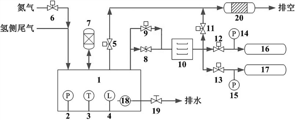
[0029] Such as figure 1 As shown, a hydrogen fuel cell dehydrogenation device disclosed in the present invention includes a hydrogen side product water tank 1 and a catalytic combustion type dehydrogenator 20 connected to the hydrogen side product water tank 1 through an emptying solenoid valve 5, and the hydrogen side tail gas is directly introduced into hydrogen Side product water tank 1, nitrogen is introduced into the hydrogen side product water tank 1 through the nitrogen solenoid valve 6, the hydrogen side product water tank 1 is provided with a water pump 18, and the water pump 18 is connected to the drain pipe through the manual valve 19, and the hydrogen side The product water tank 1 is also respectively provided with a pressure sensor 2, a temperature sensor 3, a liquid level sensor 4 and an oxygen concentration analyzer 7. The hydrogen-side product water tank 1 is connected with a dryer 10 through a pressure relief valve 8, and the pressure relief valve 8 is connecte...

Embodiment 2

[0035]The difference from Example 1 is that it is divided into four lines at the end, three of which are hydrogen elimination pipelines, leading to three small alloy hydrogen storage tanks, and solenoid valves and pressure sensors are installed on the pipelines. value in turn to eliminate hydrogen in turn; the fourth is the overpressure discharge pipeline, which is connected in series with the solenoid valve 11 and then introduced into the catalytic combustion hydrogen eliminater 20.

[0036] For a higher plateau pressure (but not exceeding the minimum back pressure for normal operation of the fuel cell) alloy hydrogen storage tank, close the solenoid valve 9 during the hydrogen elimination process, and when the hydrogen side product water tank 1 accumulates hydrogen pressure rises to the opening pressure of the pressure relief valve 8 At this time, the hydrogen gas from the hydrogen side of the fuel cell is discharged intermittently and absorbed by the alloy hydrogen storage t...


PUM


Abstract

The invention discloses a hydrogen elimination device for a hydrogen fuel cell. The hydrogen elimination device comprises main parts such as a hydrogen side product water tank, a pressure sensor, a temperature sensor, a liquid level sensor, an electromagnetic valve, an oxygen concentration analyzer, a dryer, an alloy hydrogen storage tank, a water pump, a manual valve and a catalytic combustion type hydrogen eliminator. The invention further discloses a hydrogen elimination method of the hydrogen fuel cell in the closed environment. In the hydrogen elimination process, the oxygen concentrationin the hydrogen side product water tank needs to be detected to judge the state of the fuel cell and ensure safety. When the liquid level is too high, water is drained through the water pump. In caseof emergency, nitrogen is introduced for purging protection. According to the hydrogen elimination method, the characteristics of the alloy hydrogen storage technology are fully utilized, the hydrogen elimination capacity per unit volume is high, safety is good, and it is guaranteed that replenishment is convenient.

Description

technical field [0001] The invention belongs to the field of fuel cells, and in particular relates to a hydrogen fuel cell dehydrogenation device and a hydrogen fuel cell dehydrogenation method in a closed environment. Background technique [0002] The hydrogen fuel cell power generation device has the advantages of high efficiency, low vibration and noise, low infrared signature, zero emission, modular design, easy installation and maintenance, etc. It is an ideal solution for future power generation devices, especially suitable for closed environments such as underwater or space. For the closed environment, the exhaust of the power generation device is strictly restricted. Although the hydrogen fuel cell power generation device has the characteristics of zero emission, there is still a small amount of exhaust gas emission on the hydrogen side due to the need for drainage and the purity of the hydrogen itself. [0003] The basic principle of the general hydrogen elimination...

Claims


Application Information

Patent Timeline
Patent Type & Authority Applications(China)
IPC IPC(8): H01M8/0662H01M8/0438H01M8/04119H01M8/04082
CPCH01M8/04156H01M8/04216H01M8/0438H01M8/0662Y02E60/50
Inventor 王振高勇王百杰王傲李浩
Owner 武汉氢能与燃料电池产业技术研究院有限公司
Why Eureka
Try Eureka