Variable diameter pyramid-type drilling powder discharge and pressure relief device

A pressure relief device, pyramid technology, applied in drill bits, drilling equipment, earthwork drilling, etc., can solve the problems of low strength of spiral cutters, changing drill bit structure, and inability to form powder discharge space, etc.

Pending Publication Date: 2020-10-23
SHANDONG UNIV OF SCI & TECH
View PDF2 Cites 0 Cited by
  • Summary
  • Abstract
  • Description
  • Claims
  • Application Information

AI Technical Summary

Problems solved by technology

[0006] CN204060516U discloses a kind of dry-type inner powder discharge drill bit, mainly adopts the discharge hole on the drill bit body to realize the discharge of dry powder, the drill bit body of this device is cylindrical, and the drill bit body is parallel to the rock wall in the rock body, and cannot form effective Therefore, the powder discharge efficiency of the drill bit is low, and the drill bit cannot be applied to the forward-type fully automatic controllable variable-diameter pressure relief connecting rod
[0007] CN108979549B discloses a dry-type internal powder discharge drill bit, which mainly uses a helical cutter and a through hole to realize the discharge of dry powder. Suitable for drilling in soft rock mass, while the strength of the helical cutter is low, resulting in poor stability of the drill bit
[0008] To sum up, the test devices in the prior art have not realized the problem of changing the structure of the drill bit for complex rock mass, nor solved the problem of fast powder discharge and fast drilling. Therefore, relevant researchers in this field are committed to developing a A variable-diameter pyramid-type drilling powder discharge and pressure relief device

Method used


Image

  • Variable diameter pyramid-type drilling powder discharge and pressure relief device
  • Variable diameter pyramid-type drilling powder discharge and pressure relief device
  • Variable diameter pyramid-type drilling powder discharge and pressure relief device

Examples


Embodiment Construction

[0040]The present invention proposes a variable-diameter pyramid-type drilling powder discharge and pressure relief device. In order to make the advantages and technical solutions of the present invention clearer and clearer, the present invention will be described in detail below in conjunction with specific examples.

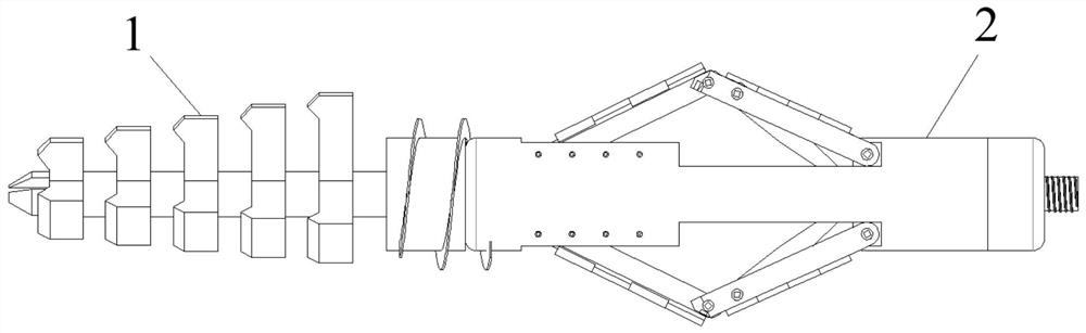
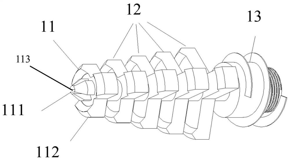
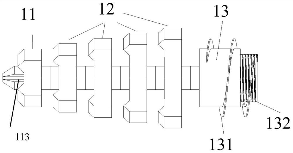
[0041] Such as figure 1 As shown, a variable-diameter pyramid-type drilling powder discharge and pressure relief device of the present invention mainly includes a pressure relief connecting rod 2 and a powder discharge pressure relief drill bit 1, and the powder discharge pressure relief drill bit 1 is installed on the front end of the pressure relief connecting rod 2 , in actual use, the rear end of the pressure relief connecting rod 2 is connected to the required drilling rod in the drilling process.

[0042] The pressure relief connecting rod 2 used in the present invention adopts the pressure relief connecting rod of the same structure in the application n...


PUM


Abstract

The invention discloses a variable diameter pyramid-type drilling powder discharge and pressure relief device, and belongs to the field of coal mining or metal mining drilling pressure relief. The device comprises a pressure relief connecting rod and a powder discharge and pressure relief drill bit; the powder discharge and pressure relief drill bit is installed at the front end of the pressure relief connecting rod, and the tail end of the pressure relief connecting rod is connected with a drill pipe; the powder discharge and pressure relief drill bit comprises a crushing exhaust pick portion, a detachable pick portion and a spiral powder discharge end cover portion which are connected from front to back in sequence; the crushing exhaust pick portion comprises a crushing exhaust pick mainbody, and axial crushing teeth, a radial pick I and a gas port, and the detachable pick portion is formed by connecting a plurality of groups of detachable pick monomers in sequence; the pick monomers are arranged in a triangular prism form to facilitate powder discharge, and the spiral powder discharge end cover portion comprises a spiral powder discharge end cover main body; and a spiral powderdischarge groove and a gas inlet are formed in the spiral powder discharge end cover main body. According to the device, quick powder discharge and quick drilling can be achieved under the effect ofhigh pressure gas at a target area in the drilling process.

Description

technical field [0001] The invention relates to the field of variable-diameter pyramid drilling pressure relief in coal mining or metal mining, in particular to a drilling powder discharge and pressure relief device. Background technique [0002] Compared with shallow mining, the stress environment of deep mining coal and rock mass is more complex, and affected by high stress, strong mining disturbance and complex geological structure, the frequency and intensity of rock bursts increase significantly. At present, the research on rock burst has achieved rich research results, but due to the "opacity" of the underground rock mass itself and the uncertainty of the stress environment in which it is located, rock burst is still a thorny problem faced by coal mine scientific and technological workers. [0003] In response to the above problems, many scholars have made great progress in the current research on the comprehensive prevention and control of rock burst, which provides g...

Claims


Application Information

Patent Timeline
Patent Type & Authority Applications(China)
IPC IPC(8): E21B10/633E21B10/32E21B10/60E21B21/16
CPCE21B10/32E21B10/60E21B10/633E21B21/16
Inventor 李杨杨张士川刘辉赵猛孙健管玉旗马强李宗凯董国良陈男
Owner SHANDONG UNIV OF SCI & TECH
Why Eureka
Try Eureka