
A kind of intelligent biomass waste degradation equipment

A biomass waste and intelligent technology, applied in the field of biomass waste treatment, can solve the problems of inability to destroy or change the internal structure of biomass, long fermentation cycle, low conversion utilization rate, etc., to avoid long fermentation treatment cycle, The feeding or discharging process is convenient, and the effect of convenient discharging and feeding

Active Publication Date: 2022-05-17
浙江嘉科新能源环保科技有限公司
View PDF8 Cites 0 Cited by
  • Summary
  • Abstract
  • Description
  • Claims
  • Application Information

AI Technical Summary

Problems solved by technology

Among them, crushing generally uses high-speed rotating blades or hammers to crush materials such as rolling, shearing, impacting, etc., but the internal structure of biomass is not changed or destroyed during the processing process, and the utilization rate of biomass conversion is very low.
Although the fermentation treatment has an excellent treatment effect, its treatment cycle is long, and it cannot quickly process the biomass waste.
[0004] For example, the utility model with the patent number CN209061281U discloses a biomass waste crushing device, which includes a base, a cutting cylinder and a crushing box. The four corners of the bottom of the base are fixed with support plates, and the inside of the base is provided with slotted holes. , one end of the base is fixedly provided with a second motor, the output end of the second motor is fixedly connected with one end of the screw feeding rod, the top of one end of the base is interspersed with one end of the second plug-in board through the second slot, and one side of the top of the base A crushing box is fixed; although the crushing device disclosed in this utility model has high crushing efficiency, mechanical crushing cannot destroy or change the internal structure of biomass, and it still has the problem of low conversion utilization rate
Another example is the utility model of patent No. CN206014920U, which discloses a reaction equipment for biomass fermentation, which belongs to the field of fermentation equipment and includes a fermenter, a feed pipe, an air outlet pipe, a feed pipe and a cloth buffer arranged at the center of the top of the fermenter. The tanks are connected, and there are four distribution pipes that go deep into the tank evenly around the distribution buffer tank. There is a stirring device inside the fermentation tank, an aeration device is fixed on the inner bottom of the fermentation tank, and a temperature sensor is installed on the fermentation tank. Probe and PH detector, the bottom of the fermenter is provided with a slag outlet, the upper side wall of the fermenter is connected with a biogas slurry return pipe, and the biogas slurry return pipe is equipped with an inter-stage heat exchanger and a biogas slurry return pump; Although the device can effectively destroy and change the internal structure of biomass through fermentation treatment of biomass waste, its conversion and utilization rate of biomass is high, but the fermentation cycle is long, and it is not suitable for rapid treatment of a large amount of biomass waste

Method used


Image

  • A kind of intelligent biomass waste degradation equipment
  • A kind of intelligent biomass waste degradation equipment
  • A kind of intelligent biomass waste degradation equipment

Examples


Embodiment 1

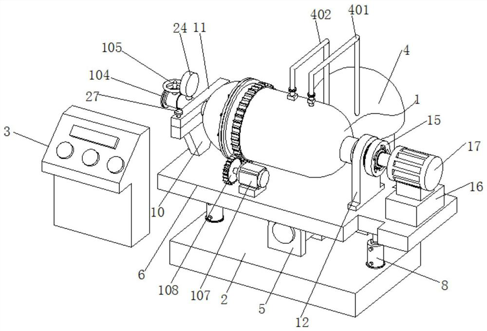
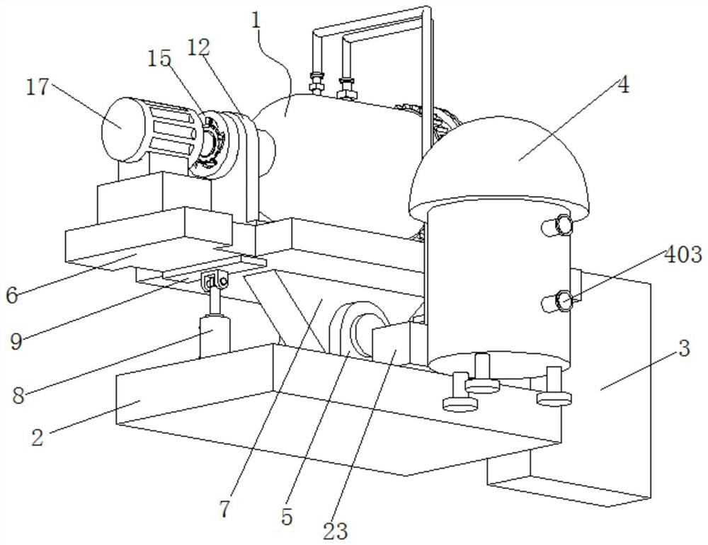
[0037] This embodiment 1 introduces a kind of intelligent biomass waste degradation equipment, refer to the attached figure 1 And attached figure 2 , its main structure includes a degradation tank 1, a base 2 and a control box 3, a rotating seat 5 is arranged at the center of the upper surface of the base 2, a loading plate 6 is arranged directly above the base 2, and the lower surface of the loading plate 6 A rotating member 7 connected to the rotating base 5 is provided, and telescopic devices 8 are fixed on the left and right ends of the rotating base 5. Specifically, the telescopic device 8 can be selected from one of an air cylinder or a hydraulic cylinder. The top of the device 8 is rotatably connected with a strip supporting plate 9, and the two strip supporting plates 9 abut against the left and right ends of the lower surface of the loading plate 6 respectively. The entire degradation tank body 1 can be tilted by the opposite extension or shortening of the two tele...

Embodiment 2

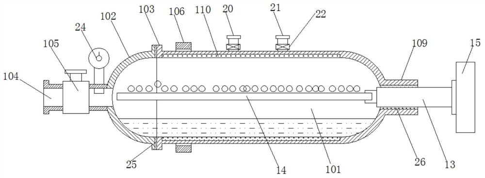
[0043] This embodiment 2 introduces the intelligent biomass waste degradation equipment improved on the basis of embodiment 1, refer to the attached figure 1 And attached figure 2 , its main structure includes a degradation tank 1, a base 2 and a control box 3, a rotating seat 5 is arranged at the center of the upper surface of the base 2, a loading plate 6 is arranged directly above the base 2, and the lower surface of the loading plate 6 A rotating member 7 connected to the rotating base 5 is provided, and telescopic devices 8 are fixed on the left and right ends of the rotating base 5. Specifically, the telescopic device 8 can be selected from one of an air cylinder or a hydraulic cylinder. The top of the device 8 is rotatably connected with a strip supporting plate 9, and the two strip supporting plates 9 abut against the left and right ends of the lower surface of the loading plate 6 respectively. The entire degradation tank body 1 can be tilted by the opposite extensi...


PUM


Abstract

The invention relates to the technical field of biomass waste treatment, in particular to an intelligent biomass waste degradation device; An object loading plate is arranged directly above the object loading plate, and the lower surface of the object loading plate is provided with a rotating member that is rotatably connected with the rotating seat, and telescopic devices are fixed on the left and right ends of the rotating seat, and the top end of the telescopic device There is a strip support plate connected by rotation, and the two strip support plates abut against the left and right ends of the lower surface of the loading plate respectively; compared with the traditional crushing effect, the treatment effect of the present invention can change or destroy the biomass inside structure; at the same time, compared with the existing fermentation tank treatment, its treatment effect is almost the same, but its treatment efficiency has been greatly improved, effectively avoiding the disadvantages of long fermentation treatment period.

Description

technical field [0001] The invention relates to the technical field of biomass waste treatment, in particular to an intelligent biomass waste degradation device. Background technique [0002] Biomass refers to all organic substances formed by the photosynthesis of green plants, including microorganisms, plants and animals, as well as their excreta, garbage and organic wastewater, etc. Biomass waste is the waste produced and consumed by humans in the process of utilizing biomass. It still belongs to the macroscopic category of biomass, but its energy density and availability have decreased significantly. [0003] Biomass waste Biomass waste can be divided into three categories according to different sources. The first is urban biomass waste, which mainly includes household kitchen waste, kitchen waste, urban manure and urban sludge; the second is agricultural waste, and the main crop straws in my country are corn straw, wheat straw and rice straw. ; The third is poultry manu...

Claims


Application Information

Patent Timeline
Patent Type & Authority Patents(China)
IPC IPC(8): B09B3/00B09B101/25
CPCB09B3/45Y02W30/40
Inventor 马尚行戴永军沈英达吴旦钧郁达飞
Owner 浙江嘉科新能源环保科技有限公司
Learn More