Method and device for treating ammonia-nitrogen wastewater and recovering ammonia

A technology for ammonia nitrogen wastewater and ammonia recovery, applied in water/sewage treatment, chemical instruments and methods, heating water/sewage treatment, etc., can solve problems such as hidden dangers of ammonia-containing steam, avoid secondary pollution, and reduce comprehensive energy consumption , the effect of reducing the condensing load

Pending Publication Date: 2020-10-27
吴嘉
View PDF5 Cites 5 Cited by
  • Summary
  • Abstract
  • Description
  • Claims
  • Application Information

AI Technical Summary

Problems solved by technology

[0006] In view of this, the object of the present invention is to provide a method and device for ammonia nitrogen wastewater treatment and ammonia recovery, using heat pump technology to save energy and reduce consumption, and the heat pump compressor pressurizes the non-toxic and harmless heat pump working medium steam, Instead of the ammonia-containing steam obtained from the deamination tower, the safety is guaranteed, and the problem of potential safety hazards in the direct pressurization of ammonia-containing steam in the prior art is solved

Method used


Image

  • Method and device for treating ammonia-nitrogen wastewater and recovering ammonia
  • Method and device for treating ammonia-nitrogen wastewater and recovering ammonia
  • Method and device for treating ammonia-nitrogen wastewater and recovering ammonia

Examples


Embodiment 1

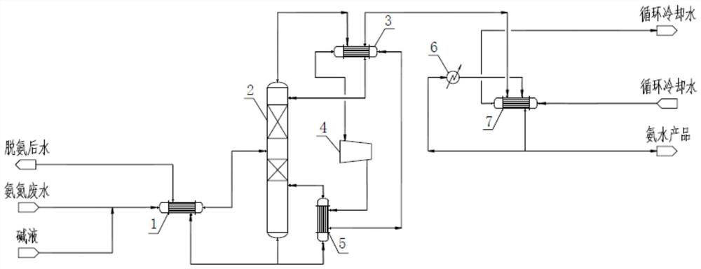
[0043] Such as figure 1 As shown, this embodiment provides an ammonia nitrogen wastewater treatment and ammonia recovery device, including a wastewater preheater 1, a ammonia removal tower 2, a heat pump condenser 3, a heat pump compressor 4, a heat pump reboiler 5, and spray liquid cooling 器6 and spray condenser 7.

[0044] The ammonia removal tower 2 is a vertical single tower body, including a rectifying section and a stripping section, and the rectifying section is located above the stripping section. Ammonia nitrogen wastewater inlet is set between the rectification section and the stripping section, the rectification section is equipped with an ammonia-containing steam outlet and a dilute ammonia water return port, and the stripping section is equipped with a water outlet and stripping steam after deamination. Inlet.

[0045] The wastewater preheater 1 is in communication with the ammonia nitrogen wastewater inlet and the deammination water outlet of the ammonia removal tower...

Embodiment 2

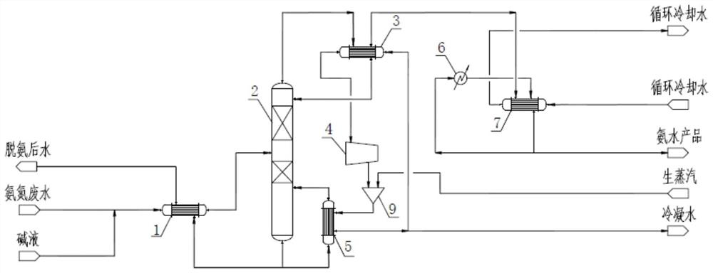
[0064] The difference between embodiment 2 and embodiment 1 in terms of equipment is that a steam mixer 9 is connected between the hot side of the heat pump compressor 4 and the heat pump reboiler 5, and a condensation is connected between the heat pump reboiler 5 and the heat pump condenser 3 Water extraction pipeline.

[0065] The difference in method is that the raw steam and the heat pump working fluid water vapor are mixed through the steam mixer 9 and passed into the heat pump reboiler 5 to supply heat to the heat pump reboiler 5; the raw steam exchanges heat with the heat pump working fluid water vapor After that, condensed water is formed, part of which is returned to the cold side of the heat pump condenser 3 as the heat pump working fluid, and the other part is produced to keep the total amount of the heat pump working fluid in the circulating state in balance.

[0066] In this embodiment, the flow of ammonia nitrogen wastewater is 30m 3 / h, the ammonia nitrogen content i...

Embodiment 3

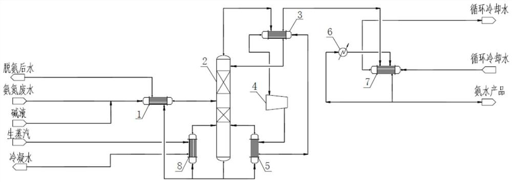
[0070] The difference between Embodiment 3 and Embodiment 1 in the device is that it also includes a raw steam reboiler 8, which uses raw steam as a heating working medium. The hot side of the raw steam reboiler 8 is connected with a heating working fluid introduction pipe and a heating working fluid extraction pipe. The cold side of the raw steam reboiler 8 is connected with the deammination tower 2 through the deammination water introduction pipe and the steam outlet pipe. The water introduction pipeline after deamination is in communication with the deamination water outlet of the deamination tower 2, and the steam outlet pipeline is in communication with another stripping steam inlet provided in the stripping section of the deamination tower 2.

[0071] The difference in method is that a raw steam reboiler 8 other than the heat pump reboiler 5 is added, and the raw steam is used as a heating working medium to provide stripping steam to the ammonia removal tower 2, specifically...


PUM


Abstract

The invention relates to a method and a device for treating ammonia-nitrogen wastewater and recovering ammonia, which belong to the technical field of industrial wastewater treatment and comprise a deamination tower, a heat pump reboiler, a heat pump condenser and a heat pump compressor. An ammonia-nitrogen wastewater feeding hole is formed between a rectifying section and a stripping section of the deamination tower, the rectifying section is provided with an ammonia-containing steam discharging hole and a dilute ammonia water backflow hole, and the stripping section is provided with a deaminated water discharging hole and a stripping steam feeding hole; a heat pump reboiler is circularly communicated between the deaminized water discharging hole and the stripping steam feeding hole; a heat pump condenser is circularly communicated between the ammonia-containing steam discharging hole and the dilute ammonia water backflow hole; and the heat pump condenser and the heat pump reboiler are circularly communicated through a heat pump compressor to form a heat pump cycle. Heat pump working medium steam is used for supplying heat to the heat pump reboiler to replace raw steam, so that energy is saved, and consumption is reduced; non-toxic and harmless heat pump working medium steam is pressurized by the heat pump compressor, so that the problem of potential safety hazards caused by direct pressurization of ammonia-containing steam in the prior art is solved.

Description

Technical field [0001] The invention belongs to the technical field of industrial wastewater treatment, and relates to a method and device for treating ammonia nitrogen wastewater and recovering ammonia. Background technique [0002] The chemical, fertilizer, pesticide, printing and dyeing, battery and other industries will produce a large amount of ammonia nitrogen wastewater in the production process, of which the ammonia nitrogen is free ammonia (NH 3 ) And ammonium ion (NH 4 + ) Exists in the form of. After the sewage containing ammonia nitrogen is discharged into the water body, the ammonia nitrogen has a high oxygen consumption and is toxic to aquatic organisms. It is oxidized to nitrite and nitrate under the action of nitrifying bacteria, which is also toxic to the human body. The state has strict regulations and restrictions on the ammonia nitrogen content in discharged wastewater. [0003] At present, ammonia nitrogen wastewater treatment methods mainly include biological...

Claims


Application Information

Patent Timeline
Patent Type & Authority Applications(China)
IPC IPC(8): C02F1/04B01D5/00C01C1/12C02F101/16
CPCC02F1/04C02F1/043B01D53/002B01D5/0036C01C1/12C02F2101/16Y02B30/52Y02P20/50Y02P20/10Y02P20/129Y02P70/10
Inventor 吴嘉
Owner 吴嘉
Why Eureka
Try Eureka