Waste gas combustion treatment device with turn-back type multi-stage rotational flow oxidation function

A waste gas combustion and treatment device technology, which is applied in the direction of combustion type, combustion equipment, combustion method, etc., can solve the problems of emission pollution and environmental pollution

Active Publication Date: 2020-10-27
湖南未名环保科技有限公司
View PDF17 Cites 0 Cited by
  • Summary
  • Abstract
  • Description
  • Claims
  • Application Information

AI Technical Summary

Problems solved by technology

[0003] The object of the present invention is to address the above problems, to provide a waste gas combustion treatment device with a turning type multi-stage swirl oxidation function, which is scientific in design, easy to use, and can fully decompose and utilize the waste gas generated by garbage combustion, completely solving the problem The problem of environmental pollution caused by combustion waste gas emission is thoroughly purified, which meets the actual production needs of enterprises for waste gas treatment after waste incineration treatment. The effect of waste combustion treatment is good, and the treatment efficiency of waste gas is high. For more than three seconds, compared with traditional processing equipment, the flue gas residence time is nearly doubled, which can fully contact the flue gas and fuel, avoid fuel waste, improve fuel utilization, save production costs for enterprises, and improve economic benefits.

Method used


Image

  • Waste gas combustion treatment device with turn-back type multi-stage rotational flow oxidation function
  • Waste gas combustion treatment device with turn-back type multi-stage rotational flow oxidation function
  • Waste gas combustion treatment device with turn-back type multi-stage rotational flow oxidation function

Examples


Embodiment Construction

[0024] In order to enable those skilled in the art to better understand the technical solution of the present invention, the present invention will be described in detail below in conjunction with the accompanying drawings. The description in this part is only exemplary and explanatory, and should not have any limiting effect on the protection scope of the present invention. .

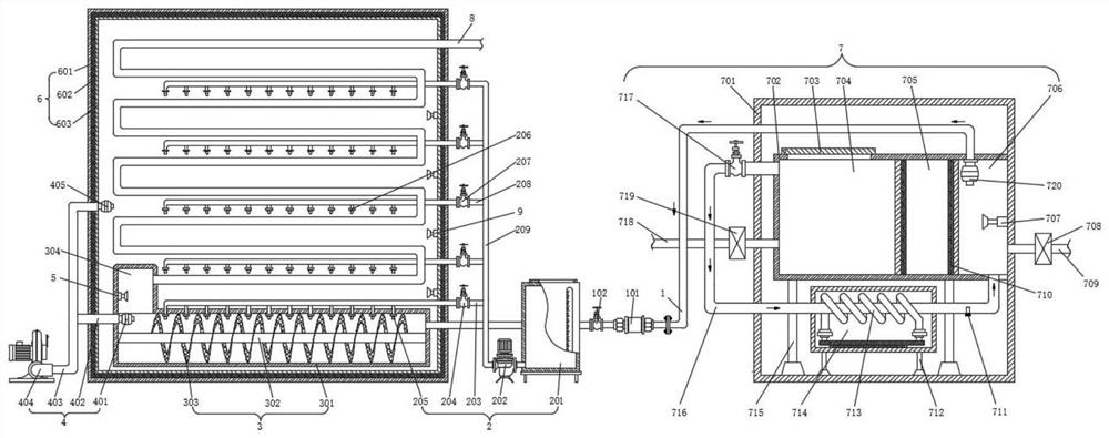
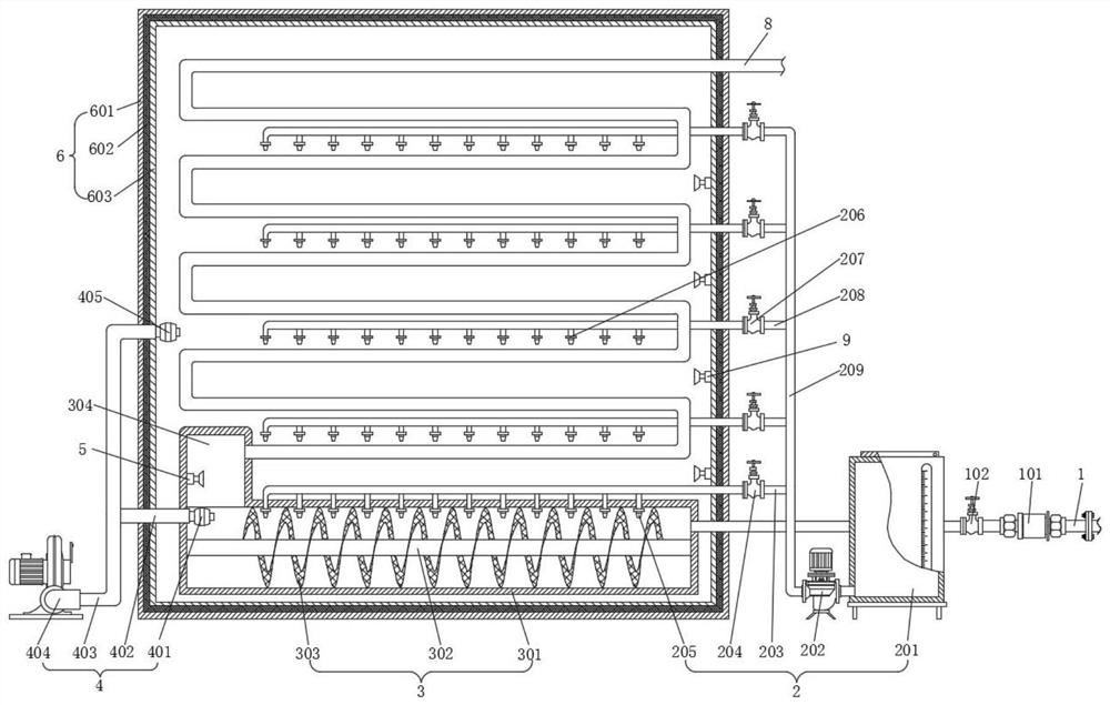
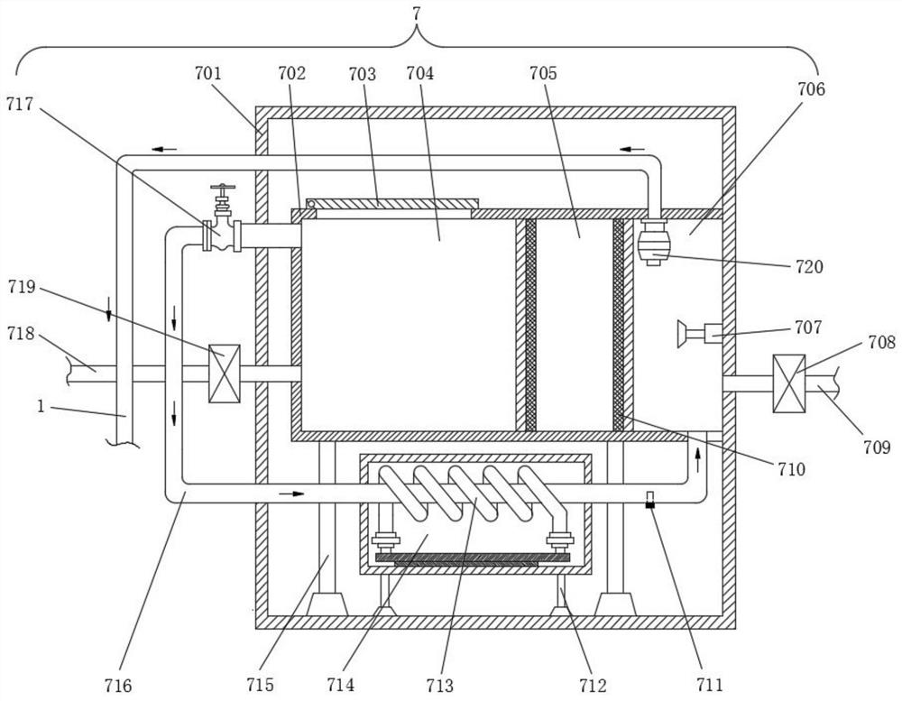
[0025] Such as Figure 1-Figure 5Shown, the concrete structure of the present invention is: it comprises garbage burning treatment module 7, and garbage burning treatment module 7 comprises combustion box body 701 and inner housing 702, and inner housing 702 inner space is arranged with garbage burning chamber 704, garbage storage Chamber 705 and exhaust gas pretreatment chamber 706, the waste gas generated by the combustion of garbage inside the garbage storage chamber 705 is transported to the exhaust gas pretreatment chamber 706 through the delivery pipeline 716, and the outside of the delivery pipe...


PUM


Abstract

The invention discloses a waste gas combustion treatment device with a turn-back type multi-stage rotational flow oxidation function, and relates to the technical field of combustion treatment. The device comprises a garbage combustion treatment module. The garbage combustion treatment module comprises a combustion box and an inner shell. A garbage combustion chamber, a garbage storage chamber anda waste gas pretreatment chamber are arranged in the inner shell. Waste gas is generated by combustion of garbage in the garbage storage chamber and is conveyed to the waste gas pretreatment chamberthrough a conveying pipeline. A heating chamber is arranged on the outer portion of the conveying pipeline. A waste gas conveying pipeline is arranged above the waste gas pretreatment chamber and penetrates through an insulation chamber body module to be connected with one end of a rotational flow shell in a rotational flow module. An inner spray head is arranged at the top of the rotational flowshell, an oxygen supply module is arranged on one side of the rotational flow shell, and an ignition chamber is arranged on one side of the rotational flow shell. By means of the device, waste gas generated by garbage combustion can be fully decomposed, the actual production requirements of enterprises for waste gas treatment after garbage combustion treatment can be met, and the treatment effectto garbage combustion waste gas is good.

Description

technical field [0001] The invention relates to the technical field of waste combustion treatment, in particular to a waste gas combustion treatment device with a turning type multi-stage swirl oxidation function. Background technique [0002] In recent years, with the improvement of people's living standards, the generation of urban domestic waste is increasing rapidly, and the annual accumulation and storage of waste is very large. If the waste disposal method is landfill, it will cause huge pollution to land resources. Waste of land resources is not conducive to agricultural development. The incineration method can maximize the effective treatment of domestic waste and occupy the least land resources. However, the incinerated waste gas is discharged directly without treatment, which will cause serious air pollution and is not conducive to the protection of the ecological environment. In the existing waste treatment technology, the waste is mainly incinerated by adding co...

Claims


Application Information

Patent Timeline
Patent Type & Authority Applications(China)
IPC IPC(8): F23G7/00F23G7/06F23G5/08F23G5/04F23G5/44F23G5/50F23L7/00F23J15/00
CPCF23G7/00F23G7/06F23G5/08F23G5/04F23G5/44F23G5/50F23L7/007F23J15/00Y02E20/34
Inventor 杨跃革李启仁明永刚唐武才郎志中舒志强
Owner 湖南未名环保科技有限公司
Why Eureka
Try Eureka