Box structure with vacuum insulating layer and refrigerator

A vacuum insulation layer and box structure technology, which is applied in household refrigerators, household appliances, cooling fluid circulation devices, etc., can solve the problems of box volume ratio reduction, increase of foam layer thickness, and production cost increase

Inactive Publication Date: 2020-10-27
AUCMA
View PDF9 Cites 2 Cited by
  • Summary
  • Abstract
  • Description
  • Claims
  • Application Information

AI Technical Summary

Problems solved by technology

The thicker the foam layer, the better the insulation effect of the refrigerator, but increasing the thickness of the foam layer will increase the production cost and reduce the volume ratio of the box

Method used


Image

  • Box structure with vacuum insulating layer and refrigerator
  • Box structure with vacuum insulating layer and refrigerator
  • Box structure with vacuum insulating layer and refrigerator

Examples


Embodiment 1

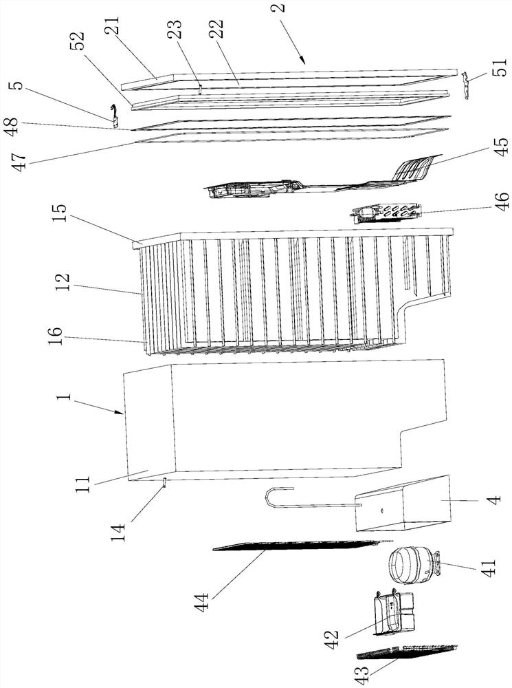
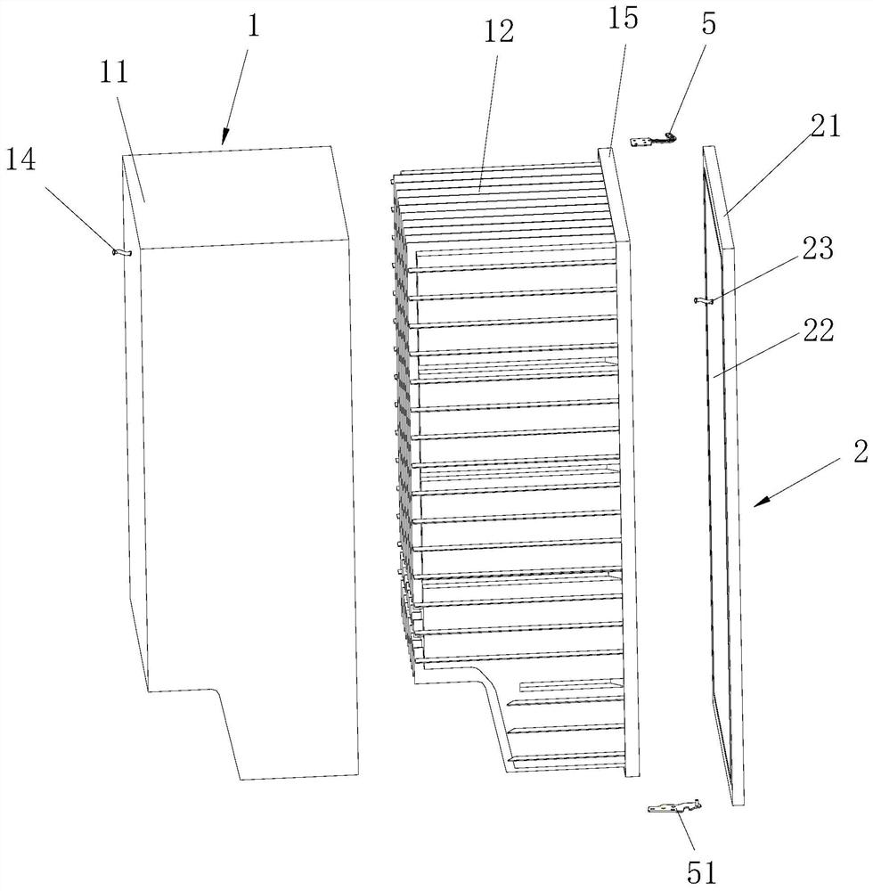
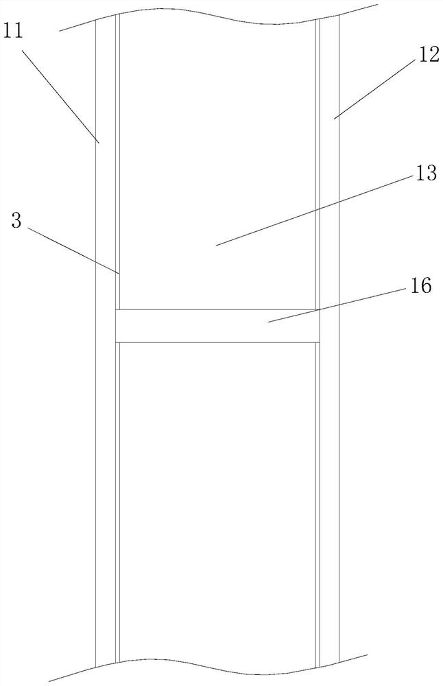
[0032] combine Figure 1 to Figure 3 , a box structure with a vacuum insulation layer, comprising a vacuum box 1 and a vacuum box door 2 connected to the front end of the vacuum box 1, the vacuum box 1 includes a box shell 11 and a box inner shell 12, the box shell 11 The first aluminum foil layer 3 is provided on the inner surface of the box inner shell 12 and the outer surface.

[0033] The inside and outside of the inner surface of the box shell 11 and the outside surface of the box inner shell 12 are determined relative to the assembly positions of the box shell 11 and the box inner shell 12. At this time, the box inner shell 12 is assembled with the box shell 11 Inside, the space inside the box inner shell 12 is the refrigerated space of the refrigerator, and this refrigerated space is the innermost end.

[0034] The box inner shell 12 is embedded in the box shell 11, and after the end of the box inner shell 12 is fixedly connected and sealed with the end of the box shel...

Embodiment 2

[0044] A refrigerator, comprising a main box shell, in which the above-mentioned box body structure with a vacuum insulation layer is connected. At least one set of the box structure of the vacuum insulation layer in each main box shell is provided, and a control main board is arranged in the main box shell.

Embodiment 3

[0046] A vacuum insulated refrigerator is provided with a vacuum box body and a vacuum box door, and the vacuum box door is composed of a box inner shell and a box outer shell. During processing, the inner surface of the box shell is covered with aluminum foil tape, and the outer surface of the box inner shell is covered with aluminum foil tape. The joint between the box inner shell and the box shell is designed as a U-shaped groove structure, and the two parts are connected together by welding to form a closed cavity. Supporting ribs for structural reinforcement are arranged between the inner shell of the box and the outer shell of the box body to ensure the structural strength of the vacuum box door.

[0047] The airtight box composed of the inner shell of the box and the outer shell of the box is evacuated to below 6Pa with a vacuum pump, and then the exhaust pipe is closed to form a vacuum airtight chamber.

[0048] The anti-dew pipe is placed in the annular groove of the...


PUM


Abstract

The invention discloses a box structure with a vacuum insulating layer and a refrigerator. The box structure comprises a vacuum box and a vacuum box door connected to the front end of the vacuum box.The vacuum box comprises a box outer shell and a box inner shell. The inner surface of the box outer shell and the outer surface of the box inner shell are each provided with a first aluminum foil layer. The box inner shell is embedded into the box outer shell. The end of the box inner shell and the end of the box outer shell are fixedly connected and sealed to form a shell cavity between the boxinner shell and the box outer shell. The box inner shell or the box outer shell is connected with a first bleeding pipe assembly. The vacuum box door comprises a door body outer board and a door bodyinner board. The inner surface of the door body outer board and the outer surface of the door body inner board are each provided with a second aluminum foil layer. The refrigerator comprises a main box shell. The box structure with the vacuum insulating layer is connected to the interior of the main box shell. The box structure is provided with the vacuum box with the better heat insulating effectand the vacuum box door with the better heat insulating effect and is novel in structure and high in practicality.

Description

technical field [0001] The invention relates to the field of refrigerators, in particular to a box structure with a vacuum insulation layer and a refrigerator. Background technique [0002] Existing refrigerators all form an insulating layer by foaming in the cabinet to achieve the purpose of keeping the refrigerator warm. The thickness of the foam layer of the refrigerator directly affects the heat leakage of the box. The thicker the foam layer, the better the insulation effect of the refrigerator, but increasing the thickness of the foam layer will lead to an increase in production costs and a decrease in the volume ratio of the box. [0003] Using a vacuum box for heat preservation, the heat transfer method of the box changes in principle, from the original foam layer heat conduction to the vacuum layer radiation heat exchange. Under the same temperature difference, the radiation heat transfer has nothing to do with the thickness of the insulation layer, but is only rel...

Claims


Application Information

Patent Timeline
Patent Type & Authority Applications(China)
IPC IPC(8): F25D11/00F25D23/02F25D23/06
CPCF25D11/00F25D23/028F25D23/062F25D2323/02
Inventor 刘悦超徐玉峰朱阳春黄玉杰张顺穆郭硕
Owner AUCMA
Why Eureka
Try Eureka