Control system of hair follicle extraction structure

A technology of controlling system and extracting structure, applied in the direction of control system, control/regulation system, control mechanical energy, etc., can solve the problems of unsatisfactory hair follicle extraction effect, hair follicle costing a lot of time and energy, and hair follicle accuracy reduction, etc. The requirements of technology and experience, the effect of few manual operation steps and high degree of automation

Active Publication Date: 2020-10-30
CHONGQING UNIV
View PDF6 Cites 5 Cited by
  • Summary
  • Abstract
  • Description
  • Claims
  • Application Information

AI Technical Summary

Problems solved by technology

With the continuous advancement of hair transplantation technology, FUE hair transplantation technology has small scars and a large number of hair transplants, and soon became the main technology of hair transplantation. However, because FUE hair transplantation is cumbersome, the work intensity is high, and it takes a long time. Manually extracting hair follicles will consume a lot of time and effort. Energy, and requires doctors to have high technology and experience to complete the extraction of hair follicles
At the same time, because the extraction of hair follicles lasts for several hours, the long-term high-intensity work will greatly reduce the accuracy of the doctor's extraction of hair follicles, resulting in unsatisfactory results of hair follicle extraction.

Method used


Image

  • Control system of hair follicle extraction structure
  • Control system of hair follicle extraction structure
  • Control system of hair follicle extraction structure

Examples


Embodiment 1

[0055] This embodiment discloses a control system for a hair follicle extraction structure, including an upper computer for controlling the hair follicle extraction structure, a control system I, a control system II, a control system III, and a control system IV.

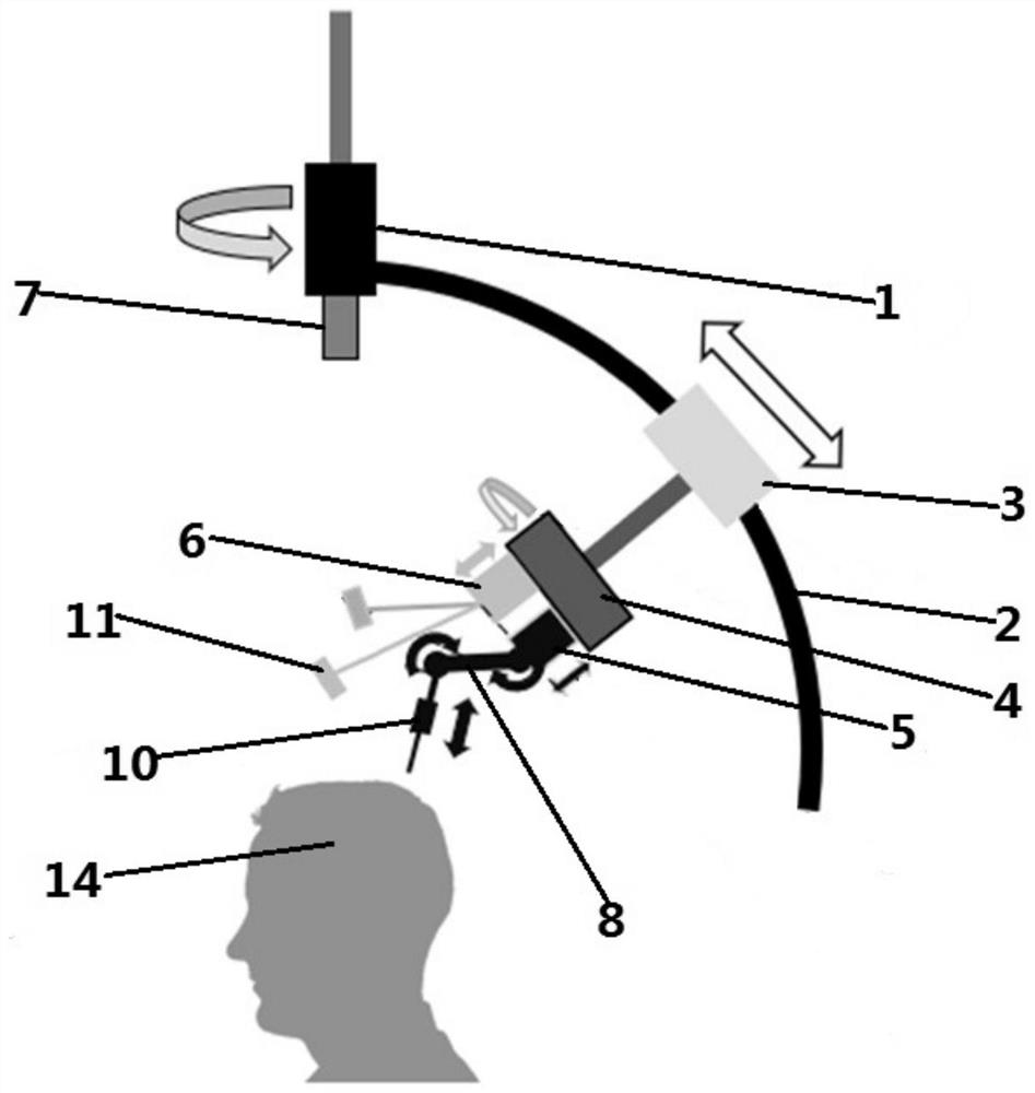
[0056] The hair follicle extraction structure includes a coarse adjustment screw 1, a sliding groove 2, a slider 3, a fine adjustment screw 4, a fine adjustment lifting part 5, an electron microscope lifting part 6, a binocular global camera 7, a connecting arm II 8, a cutter 10, and an electron microscope 11. . figure 1 The adjustment direction of each component is shown.

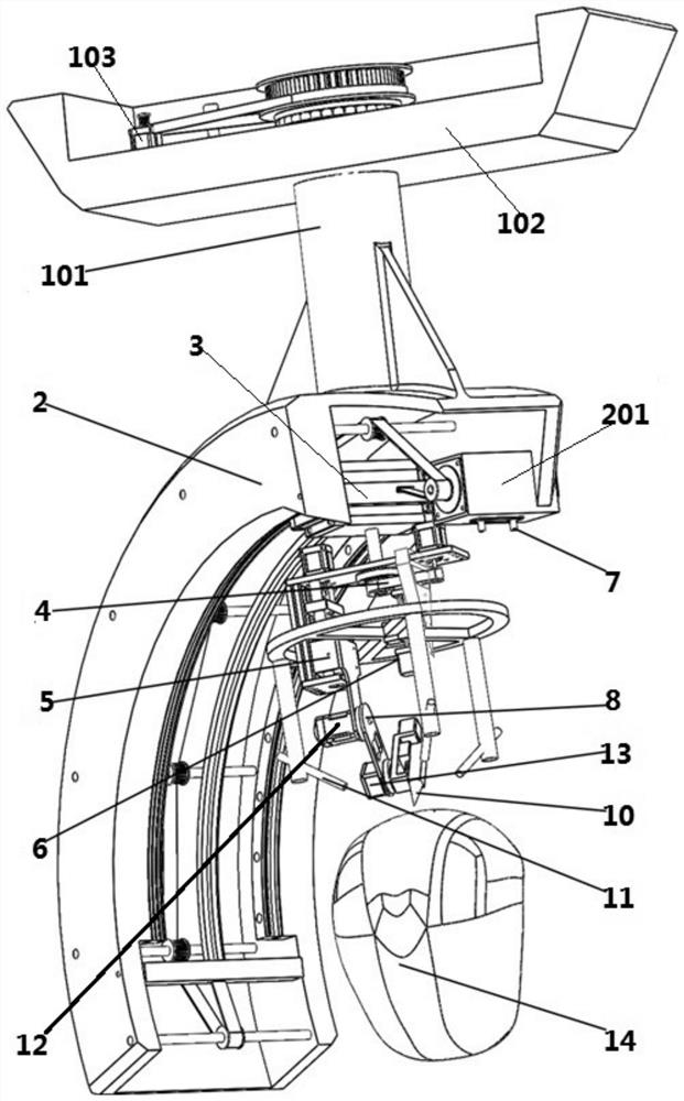
[0057] See figure 2 The coarse adjustment screw 1 includes a rotating rod 101, a platform 102 and a stepping motor I 103. The platform 102 is provided with a through hole I for the rotating rod 101 to pass through. The rotating rod 101 is vertically arranged, and the upper end of the rotating rod 101 passes through The through hole I on the platform...

Embodiment 2

[0085] This embodiment discloses a control system for a hair follicle extraction structure, including an upper computer for controlling the hair follicle extraction structure, a control system I, a control system II, a control system III, and a control system IV.

[0086] The hair follicle extraction structure includes a coarse adjustment screw 1, a sliding groove 2, a slider 3, a fine adjustment screw 4, a fine adjustment lifting part 5, an electron microscope lifting part 6, a binocular global camera 7, a connecting arm II 8, a cutter 10, and an electron microscope 11. .

[0087] See figure 2 The coarse adjustment screw 1 includes a rotating rod 101, a platform 102 and a stepping motor I 103. The platform 102 is provided with a through hole I for the rotating rod 101 to pass through. The rotating rod 101 is vertically arranged, and the upper end of the rotating rod 101 passes through The through hole I on the platform 102 extends out of the upper surface of the platform 102, and...

Embodiment 3

[0109] The main structure of this embodiment is the same as that of Embodiment 2. For further details, see Figure 8 The control system I also includes an encoder I and an encoder II, and the encoder I and the encoder II are respectively arranged on the stepper motor I103 and the stepper motor II201. The encoder I and the encoder II collect the rotation information of the stepper motor I103 and the stepper motor II201 respectively and send them to the single-chip microcomputer I, and the single-chip microcomputer I feeds back the rotation information to the upper computer.

[0110] See Picture 9 The control system II also includes an encoder III and an encoder IV, and the encoder III and the encoder IV are respectively arranged on the stepper motor III405 and the stepper motor IV601. The encoder III and the encoder IV II collect the rotation information of the stepping motor III 405 and the stepping motor IV 601 respectively and send them to the single-chip microcomputer II, and ...


PUM


Abstract

The invention discloses a control system of a hair follicle extraction structure, which comprises an upper computer for controlling the hair follicle extraction structure and four sub-control systems,and the four sub-control systems are all in communication connection with the upper computer. Wherein the first sub-control system controls a rough adjustment screw and an arc-shaped sliding block ofthe hair follicle extraction structure, the second sub-control system controls a fine adjustment screw and an electron microscope lifting component, the third sub-control system controls a fine adjustment lifting component, a shoulder joint and an elbow joint, and the fourth sub-control system controls a tool bit to stretch out and draw back to extract hair follicles. The working process of the telescopic control system is shot and guided by a binocular global camera and an electron microscope. The hair follicle extractor is high in automation degree and capable of continuously extracting hair follicles, and the working intensity of an operator is reduced; according to the hair follicle extractor, target hair follicles can be accurately extracted, damage to the scalp of a user is avoided,and the working efficiency is improved; meanwhile, the manual operation steps are few and simple, and the requirements for the technology and experience of operators are lowered.

Description

Technical field [0001] The invention relates to a control system for a hair follicle extraction structure. Background technique [0002] With the increase in life pressure, more and more people suffer from hair loss. According to surveys, in East Asia, the proportion of people with hair loss in the total population is as high as 1:5, so hair transplantation has a very good market prospect. With the continuous advancement of hair transplant technology, FUE hair transplant technology has small scars and a large number of hair transplants. It will soon become the main technology for hair transplantation. However, because FUE hair transplantation is cumbersome, the work intensity is high, and it takes a long time, manual hair follicle extraction will consume a lot of time and Energy, and requires doctors to have higher skills and experience to complete hair follicle extraction. At the same time, since the extraction time of hair follicles is as long as several hours, long-term and h...

Claims


Application Information

Patent Timeline
Patent Type & Authority Applications(China)
IPC IPC(8): A61B17/00G05D27/02H02K37/24H02K7/10H02K7/06H02P8/40H04N7/18
CPCA61B17/00G05D27/02H02K37/24H02K7/10H02K7/1004H02K7/06H02P8/40H04N7/181A61B2017/00752Y02P90/02
Inventor 李奇敏王哲朱骏野邓鈃中
Owner CHONGQING UNIV
Why Eureka
Try Eureka