
Industrial wastewater treatment equipment

A technology for treating equipment and industrial wastewater, which is applied in water/sewage treatment equipment, multi-stage water treatment, water/sewage treatment, etc. It can solve the problems of reduced water flow velocity, reduced treatment effect, filter blockage, etc., and can increase the rotation rate , improve the service life, increase the effect of the gap

Inactive Publication Date: 2020-10-30
大连汉唐盛世传媒科技有限公司
View PDF0 Cites 0 Cited by
  • Summary
  • Abstract
  • Description
  • Claims
  • Application Information

AI Technical Summary

Problems solved by technology

[0003] For the above-mentioned dyeing and printing wastewater treatment methods, precipitation method and filtration method are generally used. The precipitation method can only target impurities that are easy to sink, and the precipitation time is long. During the transfer process of dyeing and printing wastewater, it is easy to stir up impurities at the bottom of the pool, and the precipitated impurities will float again. If the filter method uses a suitable gauze to simply filter it, it is easy to cause blockage to the filter screen, which reduces the flow rate of the water, and the filtered impurities are entangled in the filter screen and are difficult to clean. The invention provides a Industrial Wastewater Treatment Equipment

Method used


Image

  • Industrial wastewater treatment equipment
  • Industrial wastewater treatment equipment
  • Industrial wastewater treatment equipment

Examples


Embodiment 1

[0026] Such as Figure 1-Figure 6 Shown:

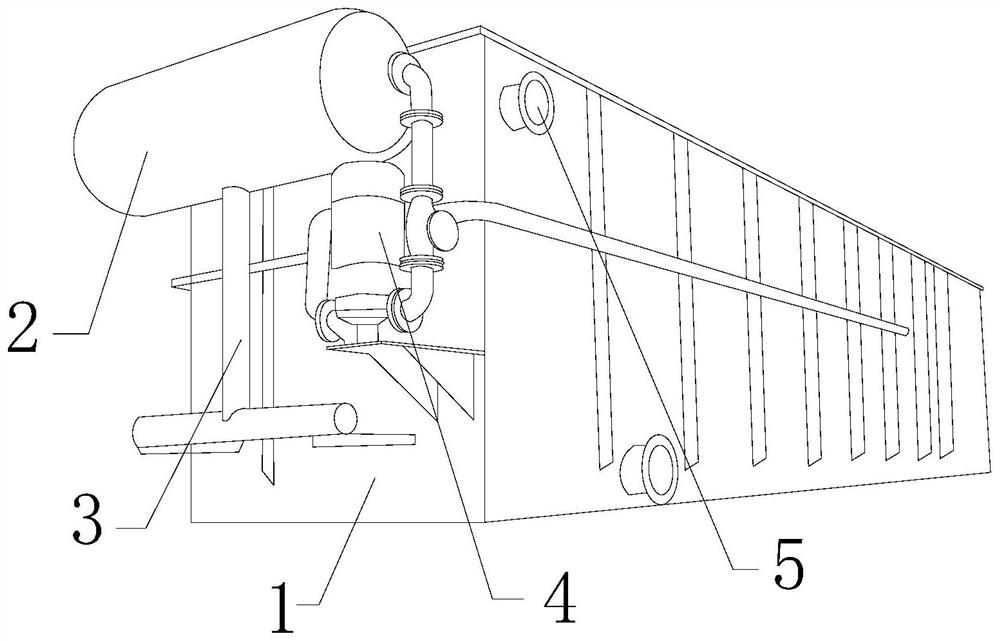
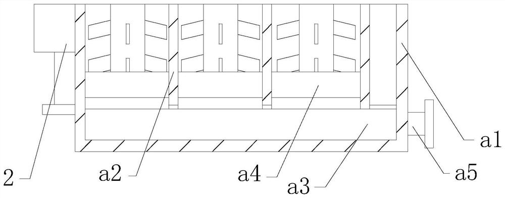
[0027] The present invention provides an industrial wastewater treatment equipment, the structure of which includes a treatment tank 1, a water supply tank 2, a connecting pipe 3, a converter 4, and an exhaust port 5, and the water supply tank 2 is embedded and connected to the treatment tank 1 with the converter 4 The front end, the exhaust port 5 is welded and connected to the position above the side of the treatment box 1, the connecting pipe 3 is flange-connected below the water supply tank 2, the connecting pipe 3 is screwed to the front end of the treatment box 1, and the treatment box 1 It mainly includes box a1, isolation plate a2, drain a3, treatment device a4, and drain pipe a5. The bottom of the inner wall of the box a1 is provided with a drain a3, and the treatment device a4 is embedded and connected to the upper side of the box a1. position, the isolation plate a2 is nested and connected between the processing devices a4...

Embodiment 2

[0035] Such as Figure 7-Figure 8 Shown:

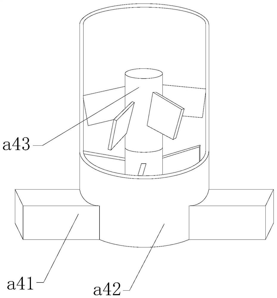
[0036] The present invention provides an industrial wastewater treatment equipment. The rotating filter tank a42 mainly includes a tank body a421, a filter plate a422, and a coupling shaft a423. The filter plate a422 is nested and connected at the bottom of the tank body a421. The axis a423 is embedded and connected to the center of the filter plate a422. The filter plate a422 has two layers and is installed in a symmetrical ring shape with the joint axis a423 as the center line, which can effectively improve the filtration efficiency and avoid the problem of dirty filtration.

[0037] Wherein, the combined shaft a423 mainly includes a support platform c1, an axis c2, a connecting plate c3, an elastic bar c4, and a contact block c5. The supporting platform c1 is embedded and connected between the filter plates a422, and the connecting plate c3 cooperates with The axis c2 is fixedly connected above the supporting platform c1, the cont...


PUM


Abstract

The invention discloses industrial wastewater treatment equipment. The equipment structurally comprises a treatment box, a water supply tank, a connecting pipe, a converter and an exhaust port, wherein the connecting pipe is in threaded connection with the front end of the treatment box; the treatment box comprises a box body, an isolation plate, a drainage channel, a treatment device and a drainage pipe; the treatment device is embedded and fixedly connected to the upper position in the box body; and the isolation plate is connected between the treatment devices in a nesting manner. Accordingto the invention, wastewater is introduced into a rotary filtering tank; stirring blades and crushing blades are driven by a rotating shaft to rotate at the same time, particle impurities in water can be impacted by the crushing blades, particle impurities continuously impact on the angle plates of the crushing blades, and blockage of larger particulate impurities in the filter cavity is avoided.Before wastewater treatment, the rotating shaft is clamped on the combining shaft firstly, so that the elastic strip pulls the contact block to be compressed backwards due to compression of the rotating shaft, the rotating shaft is further clamped in the middle section of the elastic strip, the rotating speed is effectively increased, and the treatment performance is improved.

Description

technical field [0001] The invention relates to the field of waste water treatment, and more specifically, relates to an industrial waste water treatment equipment. Background technique [0002] The wastewater produced by dyeing and printing is one of the more seriously polluted wastewater in the industry, and its discharge accounts for one tenth of the total discharge of industrial wastewater. Part of the dyeing and printing wastewater will be doped with an impurity called dye balls. Impurities are in a round shape and are heavy in weight. At present, the treatment method of dyeing and printing wastewater generally adopts the filtration method, and the filtration method uses a suitable gauze to simply filter it. The impurities in the round state are easily blocked in the filter when filtering On the hole, resulting in difficult flow of water flow, resulting in reduced wastewater filtration capacity. Contents of the invention [0003] For the above-mentioned dyeing and pr...

Claims


Application Information

Patent Timeline
IPC IPC(8): C02F1/00B02C13/18
CPCB02C13/18C02F1/001C02F2201/002C02F2201/004C02F2301/08C02F2303/14
Inventor 黄聪明
Owner 大连汉唐盛世传媒科技有限公司
Learn More