
Solar distillation unit and distillation method

A technology of distillation unit and solar energy, which is applied in the field of solar distillation unit and distillation, and can solve problems such as difficulty in realizing high-efficiency solar energy acceptance and utilization, limitation of forward heat and mass transfer direction, and reduction of evaporation rate.

Active Publication Date: 2020-10-30
BEIJING INSTITUTE OF TECHNOLOGYGY
View PDF7 Cites 1 Cited by
  • Summary
  • Abstract
  • Description
  • Claims
  • Application Information

AI Technical Summary

Problems solved by technology

When the device runs for a long time, as the water in the water-absorbing material evaporates, the salt concentration in the material increases and even crystallizes, which blocks the pores of the material, reduces the evaporation rate, and affects the water production of the device.
In the fully passive device, the solution to this problem is still the free diffusion of concentrated salt, and the rate is slow, which also severely limits the large-scale design of this type of distillation device
Second, the limitation of forward heat and mass transfer direction
As we all know, hot steam is naturally convected upwards, so the existing distillation devices are often heat transfer upwards or sideways, so that the sunlight receiving surface is below the distillation device, which itself is opposite to the direction of natural light, and it is difficult to achieve high-efficiency solar energy reception and utilization. Restricting the development of solar desalination

Method used


Image

  • Solar distillation unit and distillation method
  • Solar distillation unit and distillation method
  • Solar distillation unit and distillation method

Examples


Embodiment Construction

[0049] Below in conjunction with accompanying drawing and embodiment the present invention will be further described:

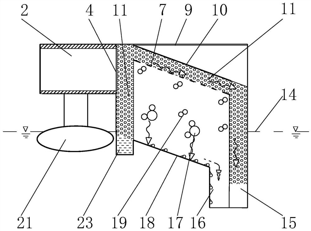
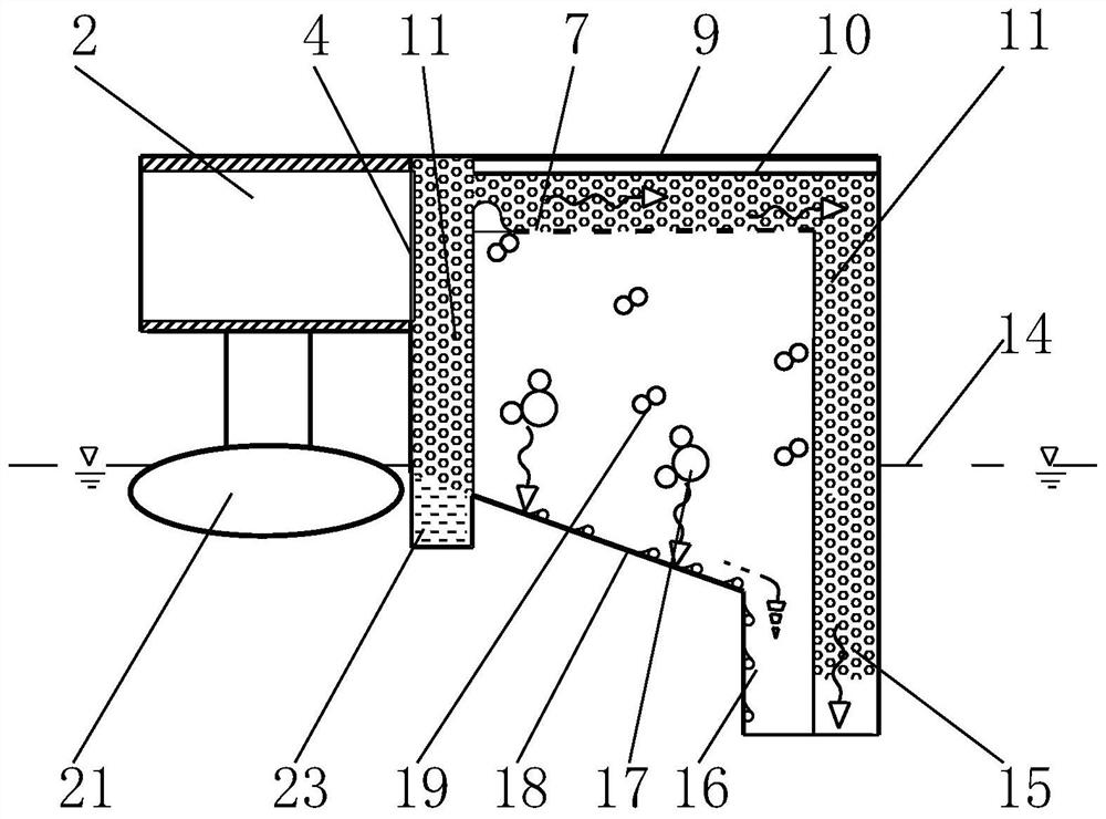
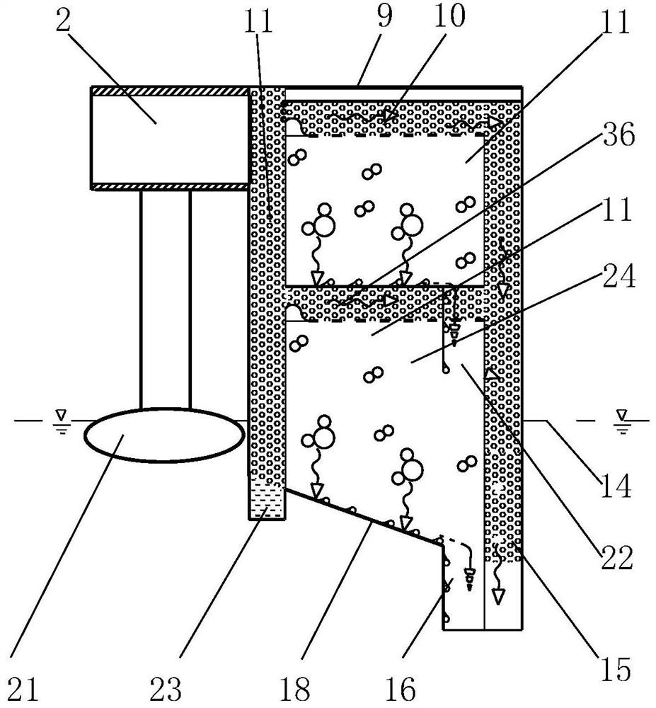
[0050] Figure 1-Figure 9 Among them, for seawater desalination technology, the application provides a solar distillation unit, including a solar heat absorbing device arranged on the top, the bottom of the solar heat absorbing device is parallel to the horizontal plane or the left side is higher than the right side and is set at an inclination angle to the horizontal plane; here , figure 1 Take the case where the bottom of the solar heat absorbing device is planar and the left side is higher than the right side and the horizontal plane is set at an inclination angle. The range of inclination angle with the horizontal plane is greater than 0 degrees and less than 90 degrees. Figure 2-Figure 9 In the figure, the bottom of the solar heat absorbing device is parallel to the horizontal plane as an example.

[0051]The solar distillation unit comprises a water...


PUM


Abstract

The invention discloses a solar distillation unit and a distillation method. The solar distillation unit comprises a water drawing cavity, an evaporation and condensation cavity and a solute-containing water cavity which are sequentially arranged from left to right. The upper ends of the evaporation and condensation cavity and the solute-containing water cavity are connected with the bottom of a sunlight heat absorption device. Hydrophilic material layers which are communicated with each other are arranged between the upper end of the evaporation and condensation cavity and the bottom of the sunlight heat absorption device and in the solute-containing water cavity. A cavity body of the evaporation and condensation cavity is filled with gas of which the molar mass is smaller than that of water molecules. A water drawing device is arranged in the water drawing cavity, the left ends of the hydrophilic material layers are communicated with the water drawing device, and a through hole formed in the left side wall of the water drawing cavity is connected with the output right end of a planar fluorescent condenser. The lower end of the evaporation and condensation cavity is connected witha pipeline for outputting condensate. The water drawing device in the distillation unit is optimized, and efficient distillation is achieved; and large-scale production is facilitated.

Description

technical field [0001] The invention relates to a distillation unit and a method, in particular to a solar distillation unit and a distillation method. Background technique [0002] Water resources are an important resource for human survival. People cannot do without water resources in production and life. [0003] In today's era, water resource stress has become a worldwide problem. As far as our country is concerned, the total amount of water resources in our country ranks among the top in the world. However, the per capita water resources are less than 2,400 cubic meters, which is only about 1 / 4 of the world's average level. It is listed by the United Nations as one of the most water-poor countries. The eastern coastal provinces of my country are economically developed, densely populated, and have few fresh water resources per capita, but consume a lot of water for production and living; in recent years, the water consumption of inland provinces in my country has also i...

Claims


Application Information

Patent Timeline
IPC IPC(8): C02F1/14C02F103/08
CPCC02F1/14C02F1/043C02F2103/08C02F2303/10Y02A20/212
Inventor 孔慧马兴龙郑宏飞
Owner BEIJING INSTITUTE OF TECHNOLOGYGY
Learn More