
Sludge filter press

A technology of sludge filter press and filter plate, which is applied in the direction of sludge treatment, water/sludge/sewage treatment, special treatment targets, etc. It can solve the problems of difficult to increase equipment pressure and centrifugal force, difficult treatment and high cost

Pending Publication Date: 2020-10-30
江苏康泰环保装备有限公司
View PDF0 Cites 1 Cited by
  • Summary
  • Abstract
  • Description
  • Claims
  • Application Information

AI Technical Summary

Problems solved by technology

[0002] At present, my country's sewage treatment enterprises produce a large amount of sludge with high water content in the process of sewage treatment. There are a large amount of perishable organic matter, bacteria, viruses and heavy metals in the sludge. These sludge must be dehydrated for subsequent treatment and disposal. , and the sludge dewatering equipment currently used by sewage treatment enterprises in my country: drum centrifuge, belt dehydrator and plate and frame filter press, due to structural limitations, it is difficult to increase the pressure and centrifugal force of the equipment, and the moisture content of the sludge after dehydration is 75 %~85%, regardless of the subsequent disposal methods such as landfill, composting and incineration, the difficulty and cost of disposal are very high

Method used


Image

  • Sludge filter press
  • Sludge filter press
  • Sludge filter press

Examples


Embodiment Construction

[0017] Embodiments of the present invention are described in detail below, examples of which are shown in the drawings, wherein the same or similar reference numerals designate the same or similar elements or elements having the same or similar functions throughout. The embodiments described below by referring to the figures are exemplary only for explaining the present invention and should not be construed as limiting the present invention.

[0018] In the description of the present invention, it should be understood that the orientations or positional relationships indicated by the terms "center", "upper", "lower", "front", "rear", "left", "right" etc. are based on the attached The orientation or positional relationship shown in the figure is only for the convenience of describing the present invention and simplifying the description, and does not indicate or imply that the referred combination or element must have a specific orientation, be constructed and operated in a spec...


PUM


Abstract

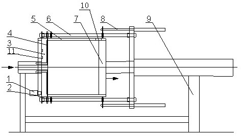
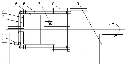
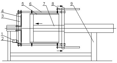
The invention discloses a sludge filter press. The sludge filter press comprises a driving motor 1, a driving planetary gear 2, a filter plate 3, filter cloth 4, a piston cylinder 5, a connecting rod6, a pressing plate hydraulic system 7, a piston cylinder hydraulic system 8 and a bracket 9; the filter plate is oppositely arranged on one side of the driving planetary gear; the filter cloth coatsthe filter plate; piston cylinders are fixedly mounted at two ends of the filter plate; a filtrate outlet is formed in the filter plate; the pressing plate hydraulic system is arranged on the side face of the piston cylinder. The filter plate, the piston cylinder and the pressing plate hydraulic system are fixedly connected through the connecting rod to form a fixed assembly body; the piston cylinder hydraulic system is mounted at the end part of the connecting rod; the driving planetary gear drives a subsequent rotating part to rotate; the pressing plate hydraulic system realizes horizontal reciprocating piston motion of a pressing plate through a pipeline hydraulic system of the pressing plate hydraulic system, sludge is subjected to filter pressing from the sludge with the water contentof 99%-98% to the sludge with the water content of 55%-75%, so that the purpose of sludge reduction is achieved, the structure is simple, the automation degree is high, and 24-hour continuous operation is realized.

Description

technical field [0001] The invention relates to a sludge filter press, in particular to a piston type sludge filter press. Background technique [0002] At present, my country's sewage treatment enterprises produce a large amount of sludge with high water content in the process of sewage treatment. There are a large amount of perishable organic matter, bacteria, viruses and heavy metals in the sludge. These sludge must be dehydrated for subsequent treatment and disposal. , and the sludge dewatering equipment currently used by sewage treatment enterprises in my country: drum centrifuge, belt dehydrator and plate and frame filter press, due to structural limitations, it is difficult to increase the pressure and centrifugal force of the equipment, and the moisture content of the sludge after dehydration is 75 %~85%, regardless of the subsequent disposal methods such as landfill, composting and incineration, the difficulty and cost of disposal are very high. Therefore, how to fur...

Claims


Application Information

Patent Timeline
Patent Type & Authority Applications(China)
IPC IPC(8): C02F11/122C02F11/147
CPCC02F11/122C02F2303/06C02F11/147
Inventor 芦伟花成巍周顺龙
Owner 江苏康泰环保装备有限公司
Learn More