Noise reduction device and outdoor unit
A technology of noise reduction and assembly holes, which is applied in the direction of refrigerators, instruments, heating methods, etc., can solve the problem of large fan noise and achieve the effect of reducing noise
- Summary
- Abstract
- Description
- Claims
- Application Information
AI Technical Summary
Problems solved by technology
Method used
Image
Examples
Embodiment 1
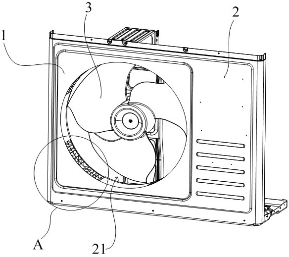
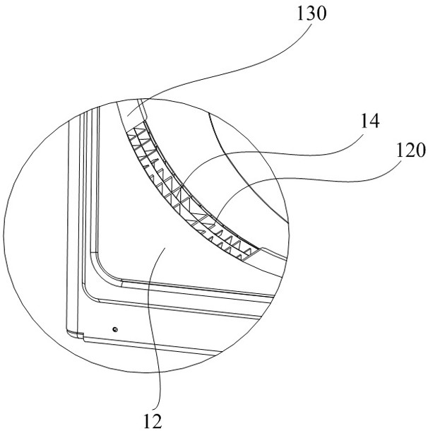
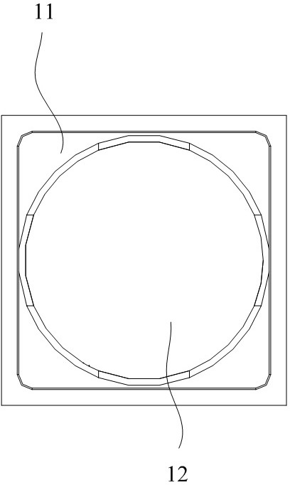
[0043] Embodiment one, such as figure 1 Shown is a structural schematic diagram of an outdoor unit, wherein the outdoor unit may be an outdoor unit of an air conditioner, an outdoor unit of a heat pump air-conditioning device, an outdoor unit of a heat pump water heater, etc., which at least includes a casing 2, and the interior of the casing 2 A fan 3 and a heat exchanger (not shown in the figure due to the angle) are provided, and an assembly hole 21 is opened at a position opposite to the fan 3 on the casing 2. When the outdoor unit is working, the heat exchanger performs heat exchange and absorbs heat. The heat or cold in the surrounding air, in order to improve the heat exchange efficiency, the fan 3 is turned on to accelerate the air flow, the air inside and outside the shell 2 circulates through the assembly hole 21, and the fan 3 is mostly used figure 1 The axial flow fan shown in , is the main noise source of the outdoor unit. The noise of the fan seriously affects pe...
Embodiment 2
[0053] Embodiment two, Figure 8 Shown is a sectional view of a U-shaped sub-muffling cavity 12a, which has a first side L1, a second side L2, and a third side L3. The depth of the sub-muffling cavity 12a is L1+L2+L3. Pass inward along the cavity surrounded by the first side L1, and part of it is reflected by the second side L2 after reaching the second side L2, and the other part continues to pass inward along the cavity surrounded by the second side L2, and reaches the third The latter part of the side L3 is reflected by the third side L3, and the other part continues to pass along the cavity surrounded by the third side L3 until it reaches the cavity bottom 123 and is reflected back by the cavity bottom 123. The reflected noise sound wave and the incident noise Sound waves are superimposed, and the depth L1+ L2+ L3 of the sub-muffling cavity 12a is set to be an odd multiple of a quarter of the wavelength of the noise to be eliminated, that is, L1+ L2+ L3=(2n-1)λ / 4. The fre...
Embodiment 3
[0061] Embodiment three, Figure 9 Shown is a sectional view of an L-shaped sub-muffling cavity 12b, which has a fourth side L4 and a fifth side L5. The depth of the sub-muffling cavity 12b is L4+L5, and the noise entering from its silencing inlet first follows the fourth side L4 The enclosed cavity passes inward, and after reaching the fifth side L5, part of it is reflected by the fifth side L5, and the other part continues to pass inward along the cavity enclosed by the fifth side L5, until it reaches the bottom 123 of the cavity, and is reflected by the bottom of the cavity. 123 is reflected back, the reflected noise sound wave is superimposed on the incident noise sound wave, and the depth L4+L5=(2n-1)λ / 4 of the sub-muffling cavity 12b is set. The frequency f of the noise to be eliminated ranges from 300Hz to 2500Hz. Since the frequency f of the noise to be eliminated is inversely proportional to the wavelength, the smaller the frequency f with noise elimination, the great...
PUM
 Abstract
Description
Claims
Application Information
 - R&D
- Intellectual Property
- Life Sciences
- Materials
- Tech Scout
- Unparalleled Data Quality
- Higher Quality Content
- 60% Fewer Hallucinations
Browse by: Latest US Patents, China's latest patents, Technical Efficacy Thesaurus, Application Domain, Technology Topic, Popular Technical Reports.
© 2025 PatSnap. All rights reserved.Legal|Privacy policy|Modern Slavery Act Transparency Statement|Sitemap|About US| Contact US: help@patsnap.com


