Energy-saving treatment process for textile printing and dyeing wastewater

A technology of textile printing and dyeing and treatment process, which is applied in the field of energy-saving treatment process of textile printing and dyeing wastewater, which can solve the problems of affecting the efficiency of continuous sedimentation of wastewater, low mixing efficiency of flocculant and wastewater, and low cleaning efficiency, so as to increase the efficiency of classification treatment, Guarantee the efficiency of static settlement and increase the effect of efficiency

Inactive Publication Date: 2020-11-03
李子生
View PDF0 Cites 1 Cited by
  • Summary
  • Abstract
  • Description
  • Claims
  • Application Information

AI Technical Summary

Problems solved by technology

However, in the prior art, the flocculant is sprayed into the pool body after the waste water is passed into the pool body, so that the flocculant reacts with the impurities in the waste water to produce flocculent suspended matter, and then settles to the bottom of the pool body after standing still, thereby completing the waste water purification. Secondary sedimentation, but the mixing efficiency of flocculant and wastewater is low. When there is a lot of sediment in the pool, it is necessary to stop the use of the pool and drain the wastewater in the pool to clean up the sediment. The cleaning efficiency is low, and the sediment needs to be cleaned. The separation equipment is reused after separation, and the separation efficiency is low, which seriously affects the efficiency of continuous sedimentation of wastewater

Method used


Image

  • Energy-saving treatment process for textile printing and dyeing wastewater
  • Energy-saving treatment process for textile printing and dyeing wastewater
  • Energy-saving treatment process for textile printing and dyeing wastewater

Examples


Embodiment approach

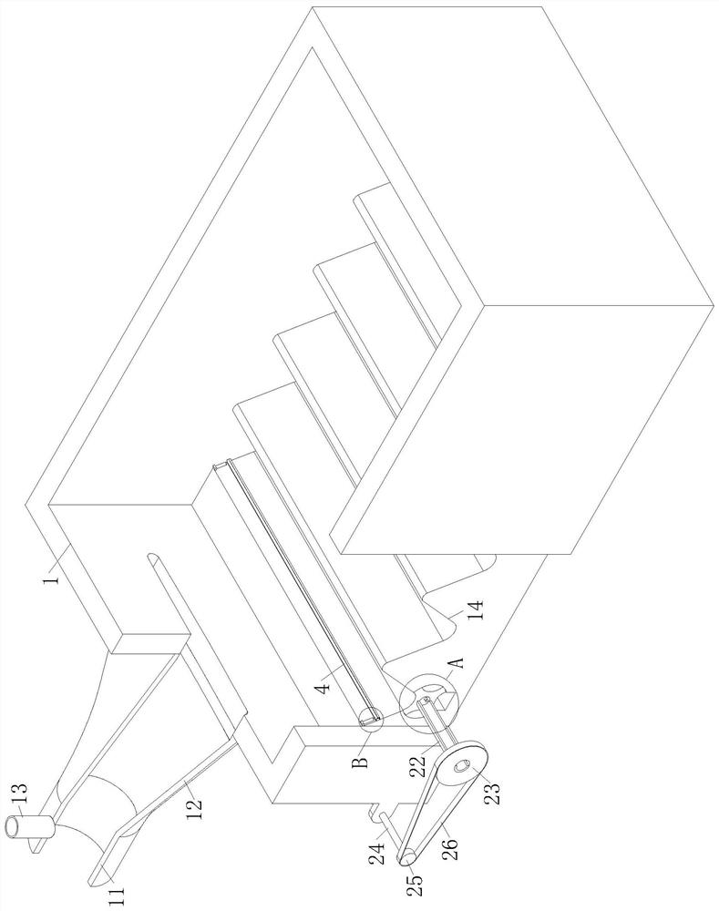
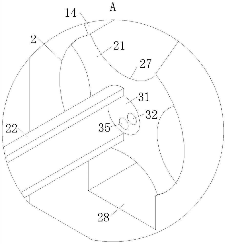
[0034] As an embodiment of the present invention, an arc-shaped chute 2 is provided at the bottom of the groove 14, and a dredging column 21 is rotatably connected in the chute 2; The pool body 1 extends to the outside of the pool body 1; the shaft sleeve 22 is fixedly connected with a No. 1 pulley 23, and the pool body 1 is connected with a drive shaft 24 through a support for rotation. The drive shaft 24 corresponds to the No. 1 pulley 23 The position is fixedly connected with the second pulley 25, and the transmission between the first pulley 23 and the second pulley 25 is driven by a belt 26; the drive shaft 24 is driven by a reduction motor fixedly connected to one side of the pool body 1; the shaft sleeve The rotating speed of 22 is lower than 10r / h; The outer circumference of the dredging column 21 is evenly distributed with a group of arc-shaped grooves 27 along the axial direction; the bottom of the chute 2 is provided with a discharge groove 28, and the discharge groo...


PUM


Abstract

The invention belongs to the technical field of wastewater treatment, and particularly relates to an energy-saving treatment process for textile printing and dyeing wastewater. A settlement tank usedin the process comprises a tank body, wherein a water inlet pipe is arranged on one side of the tank body and is communicated with the tank body through a connecting pipe; one end, close to the tank body, of the connecting pipe is in flat gradual transition, so that the distribution uniformity of wastewater after being introduced into the tank body is improved; the water inlet pipe is communicatedwith a branch pipe, and the branch pipe is communicated with a flocculating agent through a valve; the tank body is provided with a group of continuously arranged wavy grooves, and sediments of different particles are classified through the wavy grooves, so that the treatment efficiency of the sediments is further improved. According to the invention, a flocculating agent is introduced into the wastewater through the branch pipe communicated with the water inlet pipe, so that the flocculating agent is matched with one end, close to the tank body, of the connecting pipe to form flat gradual transition; therefore, the wastewater in the water inlet pipe and the flocculating agent uniformly form a stratospheric layer, the dispersion uniformity of the wastewater in the tank body is improved, and the sedimentation efficiency of the flocculating agent is further improved.

Description

technical field [0001] The invention belongs to the technical field of wastewater treatment, in particular to an energy-saving treatment process for textile printing and dyeing wastewater. Background technique [0002] Slope printing and dyeing wastewater refers to the wastewater discharged from the pretreatment, dyeing, printing and finishing of cotton, wool, hemp, silk chemical fiber or blended products. It has high concentration of organic pollutants, poor biodegradability and high chroma. , Contains toxic and harmful ingredients, large changes in water quality, and complex ingredients. In the existing printing and dyeing wastewater treatment methods, sewage treatment agents are generally used. The existing sewage treatment agents mainly include chemical and biological. However, when dealing with printing and dyeing wastewater, there are two existing processes The problem of unreasonable selection, matching and addition methods of various sewage treatment agents will eve...

Claims


Application Information

Patent Timeline
Patent Type & Authority Applications(China)
IPC IPC(8): C02F9/04C02F103/30
CPCC02F1/001C02F1/50C02F1/52C02F1/5281C02F1/66C02F7/00C02F9/00C02F2001/007C02F2103/30C02F2301/08C02F2303/14
Inventor 李子生李洋
Owner 李子生
Why Eureka
Try Eureka