Slow cutter servo cutter path and design method thereof

A tool path and path technology, which is applied to the field of free-form surface machining with a single-point diamond lathe with slow tool servo, can solve the problems of the machine tool being unable to respond, the machining efficiency is low, and the tracking trajectory error becomes large, and the calculation is simple and convenient. High machining efficiency and the effect of machining accuracy

Active Publication Date: 2020-11-03
SUZHOU UNIV OF SCI & TECH
View PDF1 Cites 3 Cited by
  • Summary
  • Abstract
  • Description
  • Claims
  • Application Information

AI Technical Summary

Problems solved by technology

However, the projections of the existing slow-tool servo machining microlens array tool paths on the θ-ρ plane are all helical lines (such as figure 1 shown), there is a sharp jump in the Z axis at the junction of the cylinder with a sudden curvature change (such as figure 2 As shown), the roughness of the surface here is relatively large, and the tool compensation requires complex three-dimensional surface curvature calculations. Due to the limitation of the corresponding frequency of the Z axis, the turning speed is

Method used


Image

  • Slow cutter servo cutter path and design method thereof
  • Slow cutter servo cutter path and design method thereof
  • Slow cutter servo cutter path and design method thereof

Examples


Example Embodiment

[0067] Example 1

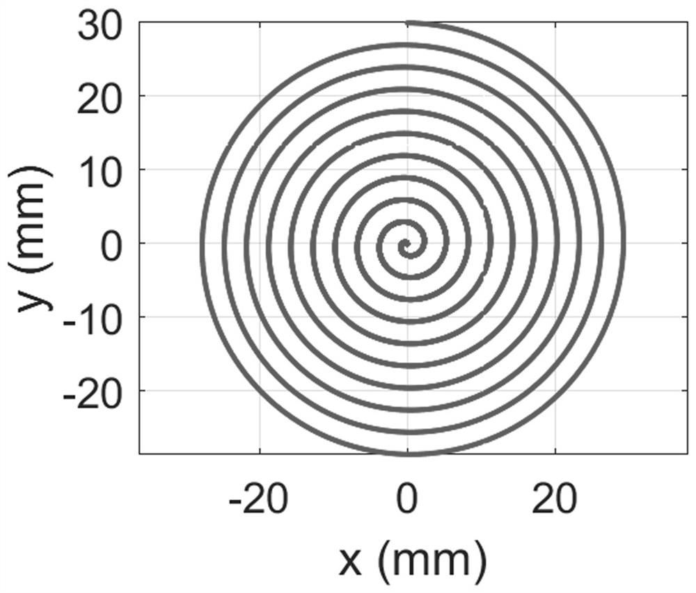
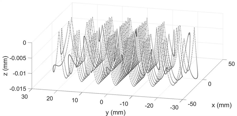
[0068] The workpiece to be processed in this embodiment is a square workpiece, and the side length 1 is 30mm. The surface shape to be processed is a parabolic cylinder array, and the width of each parabolic cylinder is 7mm. Figure 5 shown. The distance d from the outermost edge of the workpiece to the center of C-axis rotation 0 It is 60mm, and the C axis rotates 20 times per minute during processing. Use the formula (2, 3) to calculate the starting polar angle and ending polar angle θ of each effective path 2 and θ 1 , use the formula (1) to calculate the polar diameter ρ of each effective path E (n, θ), solve the equation group (11) to get the polar radius polynomial coefficient c of each transition path m , so that the polar diameter ρ of each transition path can be obtained by formula (4) T (n, θ), use the formula (12, 13) to calculate the z value of each effective path and transition path. In order to display the trajectory of the tool path, the...

Example Embodiment

[0074] Example 2

[0075] The difference between this example and Example 1 is that there are four effective paths in one path cycle, and the centers of the effective paths are located at the four positions where the polar angle θ is 0, π / 2, π and 3π / 2, and the free-form surfaces at the four positions The shape is exactly the same, and the technical scheme proposed by the invention is used to generate four transition paths to smoothly connect four effective paths. Figure 13 is the projection of the tool path on the θ-ρ plane in this embodiment. Figure 14 It is the relationship curve between the X-axis position and the polar angle when the tool path is running on the lathe in this embodiment, and the change curve of the X-axis position in the figure is closer to a sinusoidal curve. Figure 15 is the relationship curve between the X-axis speed and the polar angle when the tool path is running on the lathe in this embodiment, Figure 16 It is the relationship curve between X-...


PUM


Abstract

The invention discloses a slow-tool servo tool path and a design method thereof. The slow-tool servo tool path is achieved on an ultra-precise single-point diamond lathe by utilizing linear motion axes X and Z and a turning main shaft C with angle positioning. The tool path is divided into a cutting zone and a non-cutting zone. In the cutting area, the cutter does linear motion relative to the machined workpiece to cut the to-be-machined workpiece; and in the non-cutting area, the cutter smoothly moves from the tail end of the previous cutting track of the cutting area to the starting point ofthe next cutting track. In the whole tool path running process, the feeding speed of the X axis of the lathe is kept smooth and continuous. The absolute value of the non-cutting area lathe X-axis feeding speed is not larger than the absolute value of the cutting area lathe X-axis feeding speed. Compared with the prior art, the cutter path designed by the invention needs a small amount of data, the processing quality is higher, and the cutter compensation calculation is simple. The design method of the tool path is provided, and the design method is simple in calculation and high in executionefficiency.

Description

technical field [0001] The invention relates to ultra-precision machining, in particular to a method for machining free-form surfaces with a single-point diamond lathe and slow tool servo. Background technique [0002] The manufacturing technology of free-form optical components can be divided into two categories: ultra-precision micro-grinding and polishing technology and ultra-precision single-point diamond cutting technology. Among them, ultra-precision single-point diamond cutting includes flying tool milling, fast tool servo turning, and slow tool servo turning technology. Fly-cutter milling has a long processing cycle, initial tool setting is difficult, and the radius of gyration of the fly-cutter milling tool limits the surface shape of the workpiece. The main problem with fast tool servo turning technology is that the travel of most fast tool devices is less than 1mm, which limits their machining range. Slow tool servo turning technology, as a method of optical fre...

Claims


Application Information

Patent Timeline
IPC IPC(8): G05B19/19
CPCG05B19/19G05B2219/34093Y02P90/02
Inventor 陈宝华唐运海吴泉英范君柳
Owner SUZHOU UNIV OF SCI & TECH
Why Eureka
Try Eureka