

Valve-group-controlling urea spraying system and control method thereof
A technology of urea injection system and valve group control, which is applied in the direction of electric control of exhaust treatment device, diagnostic device of exhaust treatment device, exhaust treatment, etc. It can solve the problems of inability to purging, residual liquid residue, poor precision, etc. problem, to achieve the effect of high cost, cost saving and high precision
- Summary
- Abstract
- Description
- Claims
- Application Information
AI Technical Summary
Problems solved by technology
Method used
Image

Examples
Embodiment 1
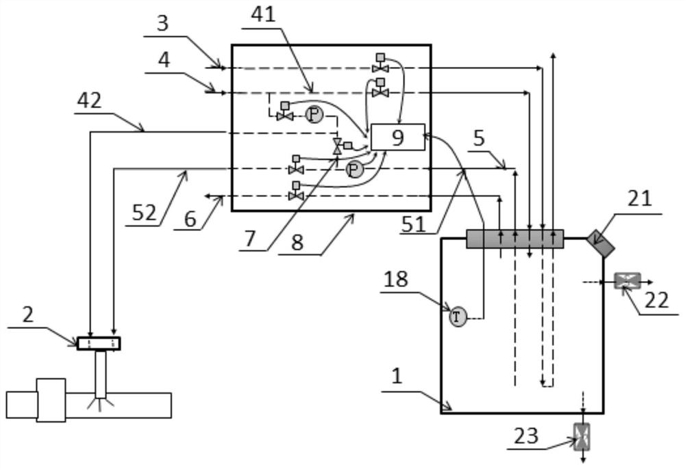
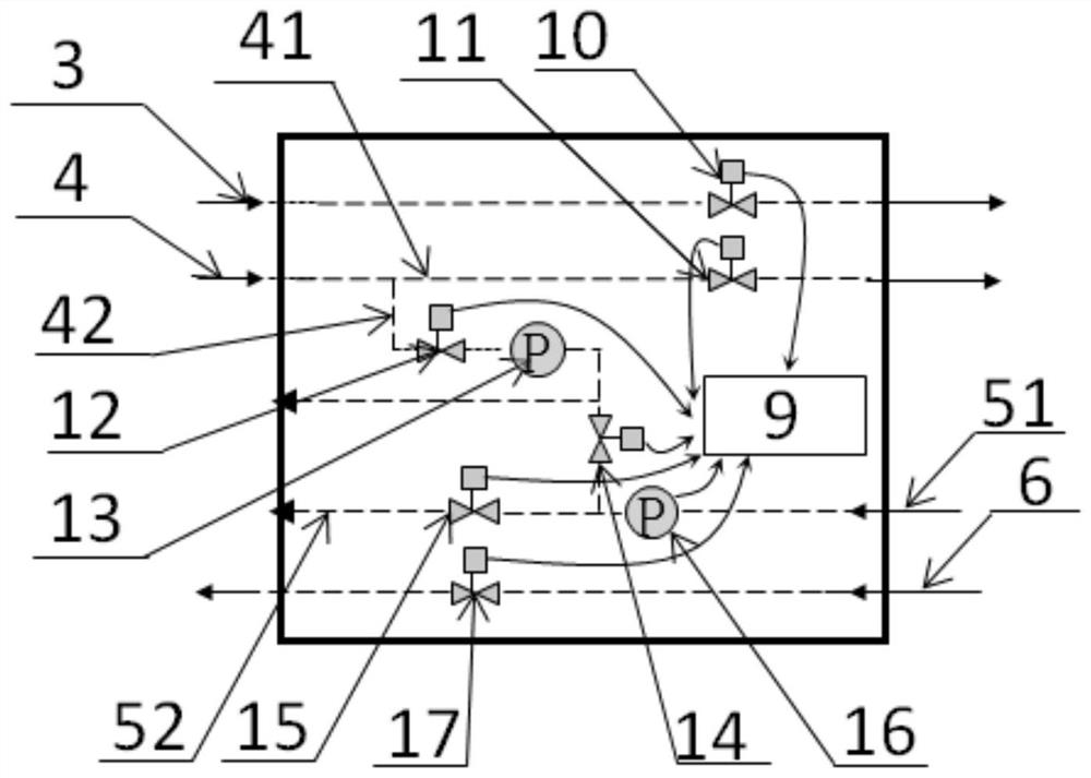
[0055] Such as Figure 1-2 As shown, a urea injection system controlled by a valve group provided by the present invention includes a urea tank 1, a urea nozzle 2, a cooling water pipeline 3, a compressed air pipeline 4, a urea pipeline 5, an air release pipeline 6, a purge pipeline 7, Valve group injection unit 8.
[0056] The connection relationship between each pipeline is: the cooling water pipeline 3 flows through the urea tank 1, and the compressed air pipeline 4 is divided into the first air pipeline 41 and the second air pipeline 41 which are connected in parallel and lead to the urea tank 1 and the urea nozzle 2 respectively after being led out from the air source. Air pipeline 42, urea pipeline 5 leads to urea nozzle 2 from urea tank 1, and deflation pipeline 6 is drawn from urea tank 1 to open atmosphere, and purge pipeline 7 is communicated with urea pipeline 5 and second air pipeline 42, and urea pipeline 5 includes Leading from the urea tank 1 to the front urea ...
Embodiment 2
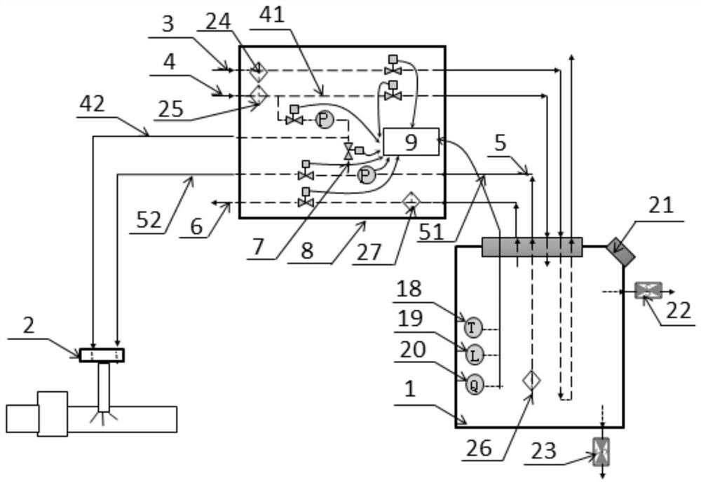
[0086] Such as image 3 As shown, the urea injection system controlled by a valve group provided in this embodiment is the same as that of Embodiment 1 except for the following structure: the urea tank 1 is also provided with a liquid level sensor 19, a concentration sensor 20, a liquid level sensor 19. The concentration sensor 20 is connected with the signal of the controller 9, the inlet of the cooling water pipeline 3 is provided with a cooling water filter 24, the inlet of the compressed air pipeline 4 is provided with an air filter 25, and the inlet of the urea pipeline 5 is provided with a urea filter 26 , The deflation pipeline 6 is provided with an atmospheric filter 27.
[0087] The control method of the urea injection system in this embodiment is the same as that in Embodiment 1, and will not be repeated here.
Embodiment 3
[0089] Such as Figure 4-5 As shown, the urea injection system controlled by a valve group provided in this embodiment has the same structure as that of Embodiment 1 except that the pressure regulating device 13 is a proportional solenoid valve.
[0090] The control method of the urea injection system in this embodiment, except for step S3, the other steps are the same as those in Embodiment 1, and will not be repeated here.
[0091] S3. Control the mixed injection of compressed air and urea
[0092] The pressure in the urea tank 1 is the target value and the controller 9 receives the urea injection command, opens the second air solenoid valve 12 and the pressure regulating device 13 to control the pressure on the second air pipeline 42, and the operation is: the second air solenoid valve 12 is fully open, adjust the proportional solenoid valve duty ratio to the required duty ratio measured under the previous normal working pressure, so that the pressure on the second air pip...
PUM
 Abstract
Description
Claims
Application Information