Sine-wave-shaped micro-channel heat exchanger with micro-cavity structures and manufacturing method thereof

A technology of microchannel heat exchanger and sine wave, which is applied in the direction of heat exchanger shell, indirect heat exchanger, heat exchanger type, etc., can solve the problems of complicated processing steps, long processing time, structural wear, etc., and achieve the processing technology Simple steps, improved heat dissipation efficiency, enhanced heat transfer effect

Inactive Publication Date: 2020-11-06
SHANGHAI JIAO TONG UNIV
View PDF5 Cites 2 Cited by
  • Summary
  • Abstract
  • Description
  • Claims
  • Application Information

AI Technical Summary

Problems solved by technology

This method has complex processing steps, long processing time, and the reliability of the microneedle fin-nanowire structure is low, and the structure will be worn and destroyed as the service time increases.

Method used


Image

  • Sine-wave-shaped micro-channel heat exchanger with micro-cavity structures and manufacturing method thereof
  • Sine-wave-shaped micro-channel heat exchanger with micro-cavity structures and manufacturing method thereof
  • Sine-wave-shaped micro-channel heat exchanger with micro-cavity structures and manufacturing method thereof

Examples


Embodiment 1

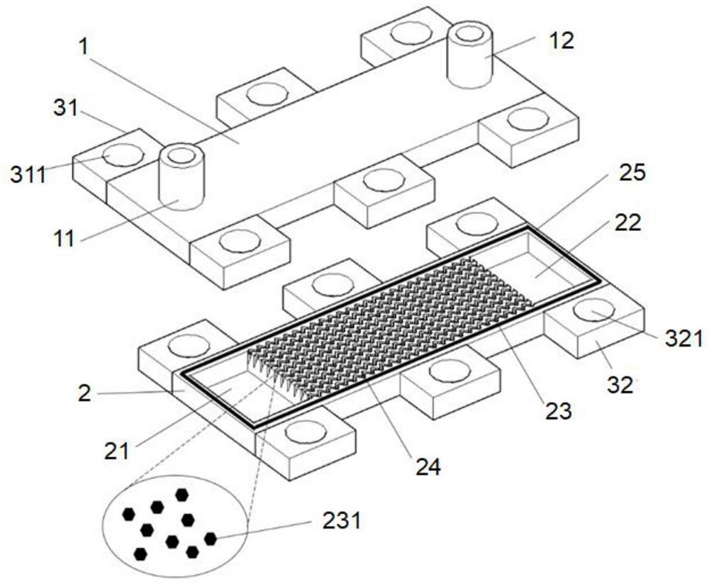
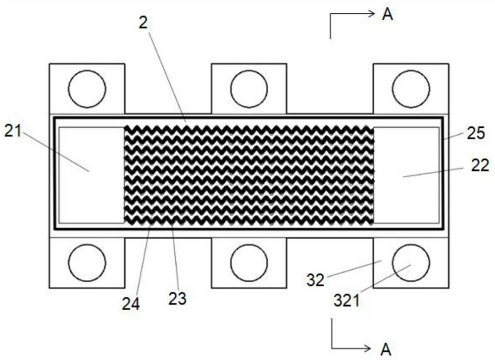
[0040] see Figure 1 to Figure 4 As shown, the present invention provides a sinusoidal microchannel heat exchanger with a micro-cavity structure, including a cover plate 1 and a microchannel heat sink 2 that are bonded together up and down, and the cover plate 1 and the microchannel heat sink 2 The room is fixedly connected by the fixing device 3;

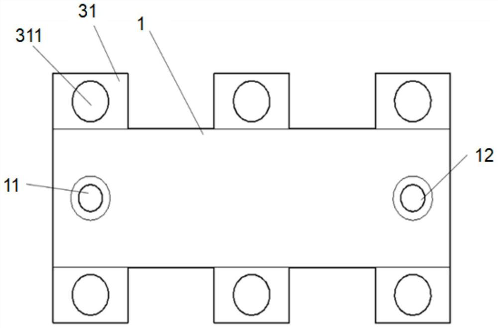
[0041] A coolant inlet 11 and a coolant outlet 12 are opened on the cover plate 1, see figure 2 As shown, the cover plate 1 is a metal cover plate. In this embodiment, the material of the cover plate 1 is copper, and the size of the cover plate 1 is 15mm*35mm. In this embodiment, the coolant inlet 11 and the coolant outlet 12 It is arranged at both ends of the long side of the cover plate 1, and the coolant inlet 11 and the coolant outlet 12 are circular columns protruding from the upper surface of the cover plate 1, and the distance between the center of the coolant inlet 11 and the left edge of the cover plate 1 is 1.5mm, 7.5mm ...

Embodiment 2

[0048] Based on the same inventive concept, see Image 6 As shown, the present invention also provides a method for manufacturing a sinusoidal wave microchannel heat exchanger with a micro-cavity structure, comprising the following steps:

[0049] S1: Provide polished first metal plate and second metal plate, the first metal plate and the second metal plate are copper plates, the size of the first metal plate is length 50mm*width 50mm*height 15mm, the second metal plate The size is length 50mm*width 50mm*height 5mm;

[0050] S2: Clamp the first metal plate on the micro-milling processing machine tool, use the micro-milling technology to process the coolant inlet and coolant outlet on the first metal plate, and make the cover plate. In this embodiment, the cover plate is long Both sides of the side are respectively symmetrically provided with a first fixed block, and a first mounting hole is provided on the first fixed block, so step S2 is specifically as follows:

[0051] Fi...


PUM

PropertyMeasurementUnit
diameteraaaaaaaaaa

Abstract

The invention discloses a sine-wave-shaped micro-channel heat exchanger with micro-cavity structures. The sine-wave-shaped micro-channel heat exchanger comprises a cover plate and a micro-channel heatsink, the cover plate and the micro-channel heat sink are vertically bonded together, a plurality of micro channels arranged in parallel at equal intervals are arranged on the micro-channel heat sink, the micro channels are sine-wave-shaped in the direction of liquid flow, cross sections of the micro channels are inverted triangles, micro rib walls which are sine-wave-shaped in the direction of the liquid flow are formed between the adjacent micro channels, cross sections of the micro rib walls are trapezoidal, the micro-cavity structures are arranged on the side wall surfaces and the bottomsurfaces of the micro-channels, the sine-wave-shaped micro channels with triangular cross-sections have secondary flows, the disturbance is enhanced, a thermal boundary layer is destroyed, the heat transfer is enhanced, coolant is stored at the bottom of a micro channel structure, the local dryout phenomenon can be effectively delayed, the backflow phenomenon is inhibited, the effect of boiling instability is reduced, the micro-cavity structures at the side wall surfaces and bottoms of the micro channels greatly increases heat transfer area, increases surface roughness and provides sufficientvaporization core for bubble nucleation, and the heat exchange is further enhanced.

Description

technical field [0001] The invention belongs to the design field of microchannel heat exchangers, in particular to a manufacturing method of a sinusoidal microchannel heat exchanger with a micro-cavity structure. Background technique [0002] With the development of miniaturization and integration of electronic equipment, the requirements for heat dissipation continue to increase. The high heat flux density caused by small area and large heat makes the use of traditional large heat dissipation equipment limited. Micro-channel heat exchangers stand out in the heat dissipation of micro-equipment due to their outstanding advantages such as high-efficiency heat dissipation, compact structure, and small footprint. Micro-channel flow boiling heat transfer makes full use of the latent heat of the coolant to meet the demand for higher heat flux density and realize the heat dissipation requirements of micro-equipment. [0003] At present, most microchannel heat exchangers use flat ...

Claims


Application Information

Patent Timeline
Patent Type & Authority Applications(China)
IPC IPC(8): F28D7/00F28F1/10F28F9/26B23K26/364B23P15/26B24B1/00
CPCB23P15/26B24B1/00B23K26/364F28D7/00F28F1/10F28F9/26
Inventor 刘振宇崔佩霖李鹏许安易
Owner SHANGHAI JIAO TONG UNIV
Why Eureka
Try Eureka