Waste recovery device for hardware processing

A waste recycling and hardware technology, which is applied in metal processing equipment, grinding/polishing safety devices, applications, etc., can solve the problems of human injury and other problems, and achieve the effect of avoiding mixing and matching, avoiding personal injury, and reducing labor intensity

Inactive Publication Date: 2020-11-13
株洲市东亨科技有限责任公司
View PDF8 Cites 0 Cited by
  • Summary
  • Abstract
  • Description
  • Claims
  • Application Information

AI Technical Summary

Problems solved by technology

[0005] The purpose of the present invention is: in order to overcome the shortcomings that manual cleaning is usually done directly by hand for convenience, and the corner waste materials that are polished are very sharp, which is easy to cause harm to people, and to provide a method that can avoid direct contact with waste materials and avoid damage to human hands. A waste recycling device for metal processing that can quickly collect and clean up waste

Method used


Image

  • Waste recovery device for hardware processing
  • Waste recovery device for hardware processing
  • Waste recovery device for hardware processing

Examples


Embodiment 1

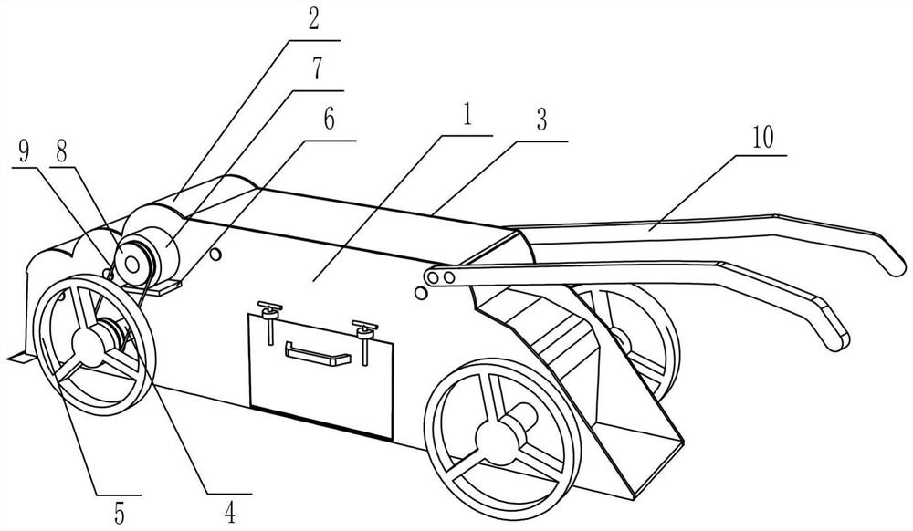
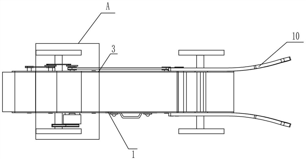
[0027] Such as Figure 1-Figure 9 As shown, a metal processing waste recycling device includes a front housing 1, a top plate 2, a feeding platform 201, a rear housing 3, a rotating shaft 4, a walking wheel 5, a supporting plate 6, a motor 7, and a pulley 8. Belt 1 9, handrail 10, transmission mechanism, compression mechanism and disassembly mechanism, the top plate 2 is consolidated on the rear side of the front shell 1, and the rear shell 3 is consolidated vertically downward at the rear end of the top plate 2, and the rear shell 3 3 is consolidated with the inner bottom of the front housing 1, and the rear housing 3 and the left inner side of the front housing 1 are consolidated with a loading table 201, and the left and right parts of the front housing 1 and the rear housing 3 are rotated by bearings. A rotating shaft 4 is connected, and the front and rear ends of the two rotating shafts 4 are connected with traveling wheels 5. The front side of the left part of the front ...

Embodiment 2

[0036] On the basis of Example 1, such as Figure 1-Figure 9 Shown, also include feeding mechanism, feeding mechanism includes rotating disk two 29, connecting rod 30, pulley three 31, belt three 32, roller one 33, toggle lever 34 and spring 35, two rotating shafts on the right side Two 12 rear ends are fixedly connected with turntable two 29, and the rear side eccentric position of two turntable two 29 is rotatably connected with connecting rod 30; Belt three 32 are wound on belt wheel three 31, and the middle part of three rotating shafts two 12 is fixedly connected with roller one 33, and three rollers one 33 are evenly spaced and slidingly connected with toggle bar 34, and each roller one 33 The toggling rods 34 are interlaced with each other, and a spring 35 is connected between the toggling rods 34 and the inner bottom end of the sliding hole.

[0037] When starting to work, the motor 7 reverses, and the motor 7 drives the overrunning clutch 11 and the rotating shaft 2 ...

Embodiment 3

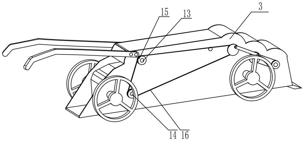
[0039] On the basis of Example 2, such as Figure 1-Figure 9 As shown, a screening mechanism is also included, and the screening mechanism also includes a roller two 36, a magnetic belt 37, a scraper plate 38 and a material leakage plate 39, and the middle part of the rotating shaft three 13 is fixedly connected with a roller two 36, and two rollers two 36 A magnetic belt 37 is installed around it, and the right part of the top plate 2 is fixedly connected with a scraper plate 38, and a material leakage plate 39 is arranged below the scraper plate 38, and the front and rear sides of the material leakage plate 39 are connected with the front casing 1 and the rear casing 3 fixed connections.

[0040] When the waste material moves to the top of the feeding platform 201, the transmission mechanism will drive the two rollers 36 to reverse, and the two rollers 36 will also drive the magnetic belt 37 to reverse, and the magnetic waste will be adsorbed on the magnetic belt 37 Go up t...


PUM


Abstract

The invention relates to a waste recovery device for hardware processing. The waste recovery device comprises a front case, a top plate, a material loading platform, a rear case, rotating shafts I, walking wheels, a support plate, a motor, a belt wheel I, a belt I, a handrail, a transmission mechanism, a compression mechanism and a disassembly mechanism. The top plate is fixedly connected to one side of the front case, the rear case is fixedly connected to one end of the top plate, the rear case is fixedly connected with the bottom of one side of the front case, the material loading platform is fixedly connected to one side of the rear case and one side of the front case, the two sides of the front case and the two sides of the rear case are all rotatably connected with the rotating shaftsI through bearings, the transmission mechanism is arranged on one side of the rear case and used for transmitting power, the compression mechanism is arranged on one side of the front case and one side of the rear case and facilitates compressing hardware waste materials, and the disassembly mechanism is arranged on one side of the front case and is used for taking out the compressed waste materials conveniently. According to the waste recovery device for hardware processing, the labor intensity of workers is reduced when the waste materials are collected, personal injury to the workers during collection is avoided, and the collection and cleaning can be rapidly realized by starting the motor.

Description

technical field [0001] The invention relates to the field of waste material recovery, in particular to a waste material recovery device for metal processing. Background technique [0002] Hardware: traditional hardware products, also known as "hardware". Refers to the five metals of gold, silver, copper, iron, and tin. After manual processing, it can be made into works of art or metal devices such as knives and swords. Hardware in modern society is more extensive, such as hardware tools, hardware parts, daily hardware, construction hardware and security products, etc. Most of the small hardware products are not final consumer goods. [0003] When processing some bearings, the surface of the bearing needs to be polished with a polishing machine. After grinding, a large amount of corner waste will be generated, and the polished corner waste will be scattered to every corner of the processing workshop and collected manually. It is very troublesome. The existing ones are manu...

Claims


Application Information

Patent Timeline
Patent Type & Authority Applications(China)
IPC IPC(8): B24B55/06B24B55/12A47L11/24A47L11/40B03C1/20B03C1/30B30B9/32B30B15/30B30B15/32
CPCA47L11/24A47L11/4013A47L11/4027B03C1/20B03C1/30B24B55/06B24B55/12B30B9/32B30B15/30B30B15/32Y02P70/10
Inventor 黄灵芝
Owner 株洲市东亨科技有限责任公司
Why Eureka
Try Eureka