Cascade H-bridge rectifier active power decoupling control method, controller and rectifier

A decoupling control and rectifier technology, applied in the direction of DC power input conversion to DC power output, AC power input conversion to DC power output, control/regulation system, etc. Problems such as poor voltage stability and unsuitability for practical engineering applications are beneficial to miniaturization, improved decoupling control accuracy, and improved system power density

Active Publication Date: 2020-11-17
SHANDONG UNIV
View PDF4 Cites 6 Cited by
  • Summary
  • Abstract
  • Description
  • Claims
  • Application Information

AI Technical Summary

Problems solved by technology

The secondary power pulsation is introduced by the single-phase AC power supply system. In engineering, parallel large capacitors or LC resonance schemes are often used to stabilize the DC side voltage, but this scheme is heavy and bulky, which restricts the increase in power density.
However, the decoupling capacitor voltage is higher than the DC side capacitor voltage, making it difficult to apply to high-voltage environments
There are also literatures that adopt the step-down APD topology in the cascade topology, but do not consider the internal stability of the decoupling capacitor when the power changes suddenly, the voltage stability of the decoupling capacitor is poor, and its decoupling control is in an open-loop state, which is harmful to the system. Large parameter dependence, not suitable for practical engineering applications

Method used


Image

  • Cascade H-bridge rectifier active power decoupling control method, controller and rectifier
  • Cascade H-bridge rectifier active power decoupling control method, controller and rectifier
  • Cascade H-bridge rectifier active power decoupling control method, controller and rectifier

Examples


Embodiment 1

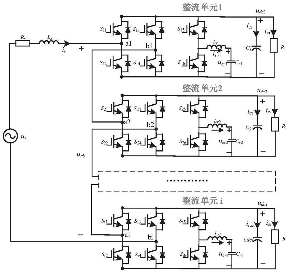
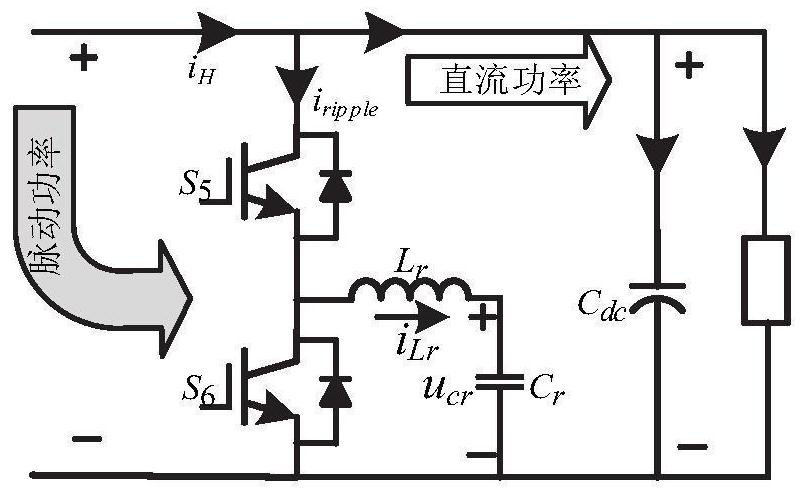
[0046] In this embodiment, the high power density single-phase CHBR system topology is as follows figure 1 As shown, the system is powered by AC power U s , Input filter inductance L s , n rectification units are cascaded to form. The rectifier unit consists of H-bridge rectifier module, power decoupling module i=1,2...n, DC filter capacitor C dci , equivalent load R dci Composition, in which the power decoupling module includes a switch tube bridge arm, a decoupling capacitor C ri and decoupling inductor L ri .

[0047] According to the unit power factor requirement of the power electronic traction transformer, the grid-side input voltage u can be set s , input current i s for,

[0048] u s =U s cosωπt (1)

[0049]

[0050] where U s , I s is the grid-side input voltage and current peak value, ω is the grid-side input voltage and current angular frequency, is the voltage-current phase difference.

[0051] Input instantaneous power p s Expressed as,

[005...

Embodiment 2

[0133] This embodiment provides a controller, including a memory and a computer program stored on the memory and operable on the processor. When the program is executed by the controller, the following steps are implemented:

[0134] Obtain the topology and operating parameters of the cascaded H-bridge rectifier, obtain the actual decoupling current setting and the expected decoupling capacitor voltage setting, and construct the decoupling bridge arm duty ratio model;

[0135] Use the decoupling bridge arm duty ratio model to generate PWM signals, and control the decoupling bridge arm switching tube action in real time;

[0136] Among them, the duty cycle model of the decoupling bridge arm is: the square of the duty cycle in Buck mode is a ratio, and the numerator of the ratio is the product of the actual decoupling current setting, the switching frequency of the decoupling module and the value of the decoupling inductance 2 times of , the denominator is the difference between...

Embodiment 3

[0148] This embodiment provides a cascaded H-bridge rectifier, which adopts the above-mentioned active power decoupling control method of the cascaded H-bridge rectifier for decoupling control. Wherein, the specific implementation process of the active power decoupling control method of the cascaded H-bridge rectifier is as described in Embodiment 1, and will not be repeated here.

[0149] In other embodiments, the cascaded H-bridge rectifier also adopts direct current control to maintain unity power factor rectification, DC bus voltage control and voltage equalization control to maintain DC side voltage stability, and generates carrier phase-shift modulation signals to control rectification in real time The action of each switch tube of the module.

[0150] This embodiment is based on the power decoupling idea rectifier control strategy, stabilizes the decoupling capacitor voltage, improves the decoupling control accuracy, effectively improves the system power density, and re...


PUM


Abstract

The invention belongs to the field of power electronic control, and provides a cascaded H-bridge rectifier active power decoupling control method, a controller and a rectifier. The cascaded H-bridge rectifier active power decoupling control method comprises the following steps of acquiring the topology and operation parameters of a cascaded H-bridge rectifier, obtaining actual decoupling current given and expected decoupling capacitor voltage given, and constructing a decoupling bridge arm duty ratio model; and generating a PWM signal by using the decoupling bridge arm duty ratio model, and controlling the action of a decoupling bridge arm switching tube in real time.

Description

technical field [0001] The invention belongs to the field of power electronic control, and in particular relates to an active power decoupling control method, a controller and a rectifier of a cascaded H-bridge rectifier. Background technique [0002] The statements in this section merely provide background information related to the present invention and do not necessarily constitute prior art. [0003] The high-speed rail transmission system consists of pantographs, traction transformers, frequency converters, and traction motors. Among them, the traditional traction transformers occupy the largest space and weight, and the number is large (7 units / column @CRH380A), which is difficult to meet the technical requirements of lightweight high-speed rail. On the basis of realizing the electrical isolation and voltage conversion functions of traditional transformers, power electronic traction transformers have the characteristics of powerful functions, small volume and weight, a...

Claims


Application Information

Patent Timeline
Patent Type & Authority Applications(China)
IPC IPC(8): H02M7/219H02M3/158
CPCH02M3/1584H02M7/219H02M1/007
Inventor 杜春水郭松郭文琛张洪亮施其国
Owner SHANDONG UNIV
Why Eureka
Try Eureka