
Sparse array method for large-spacing wide-angle scanning millimeter wave phased-array antenna

A phased array antenna and wide-angle scanning technology, which is applied in the field of wide-angle sparse arrays, can solve the problems of local dense distribution of units, many unknowns, and large calculations, and achieve simple and time-saving design methods and macro-uniform grids , the effect of uniform distribution of units

Inactive Publication Date: 2020-11-20
10TH RES INST OF CETC
View PDF6 Cites 6 Cited by
  • Summary
  • Abstract
  • Description
  • Claims
  • Application Information

AI Technical Summary

Problems solved by technology

In traditional engineering, genetic algorithm and particle swarm algorithm are often used to find the global optimal random array. Since there is no obvious mathematical and physical correspondence, it leads to many unknowns, large amount of calculation, and slow convergence.
Moreover, the sparse arrays designed by traditional optimization algorithms are usually locally densely distributed and not uniform enough. In order to reduce the unknown quantity, the arrays are often simplified, such as random arrays of sub-arrays, but the results are not ideal, and it is difficult to put them into engineering applications.
In addition, the traditional sparse array only considers the realization of electrical performance, and usually does not consider the macroscopic symmetry of the array grid, making it difficult to realize large-scale array back-end circuits.

Method used


Image

  • Sparse array method for large-spacing wide-angle scanning millimeter wave phased-array antenna
  • Sparse array method for large-spacing wide-angle scanning millimeter wave phased-array antenna
  • Sparse array method for large-spacing wide-angle scanning millimeter wave phased-array antenna

Examples


Embodiment Construction

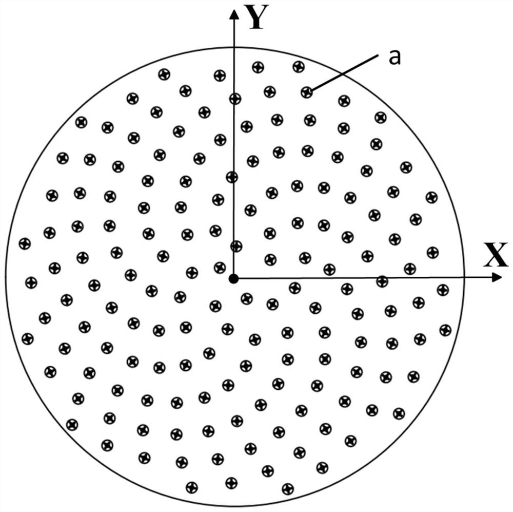
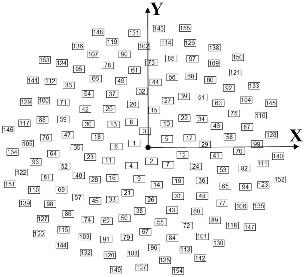
[0020] refer to figure 1 , figure 2 . According to the present invention, a symmetrical vibrator antenna is adopted, and a Cartesian coordinate system is constructed with the center of the array as the coordinate origin, and the coordinate position of the antenna unit is calculated according to the Fibonacci grid; according to the wavelength λ corresponding to the operating frequency of the antenna 0 , select the helix angle growth coefficient, and calculate the position coordinates of n antenna elements according to the unit of meters and the Fibonacci number helix formula Based on the random arrangement of the circular sparse array, set the Fibonacci grid antenna unit number, and use the Fibonacci spiral curve composition method to arrange the antenna units aperiodically; arrange n antenna units along the Fibonacci spiral to form The non-equidistant involute helical large-pitch wide-angle scanning millimeter-wave phased array that expands at equal intervals with the ...


PUM


Abstract

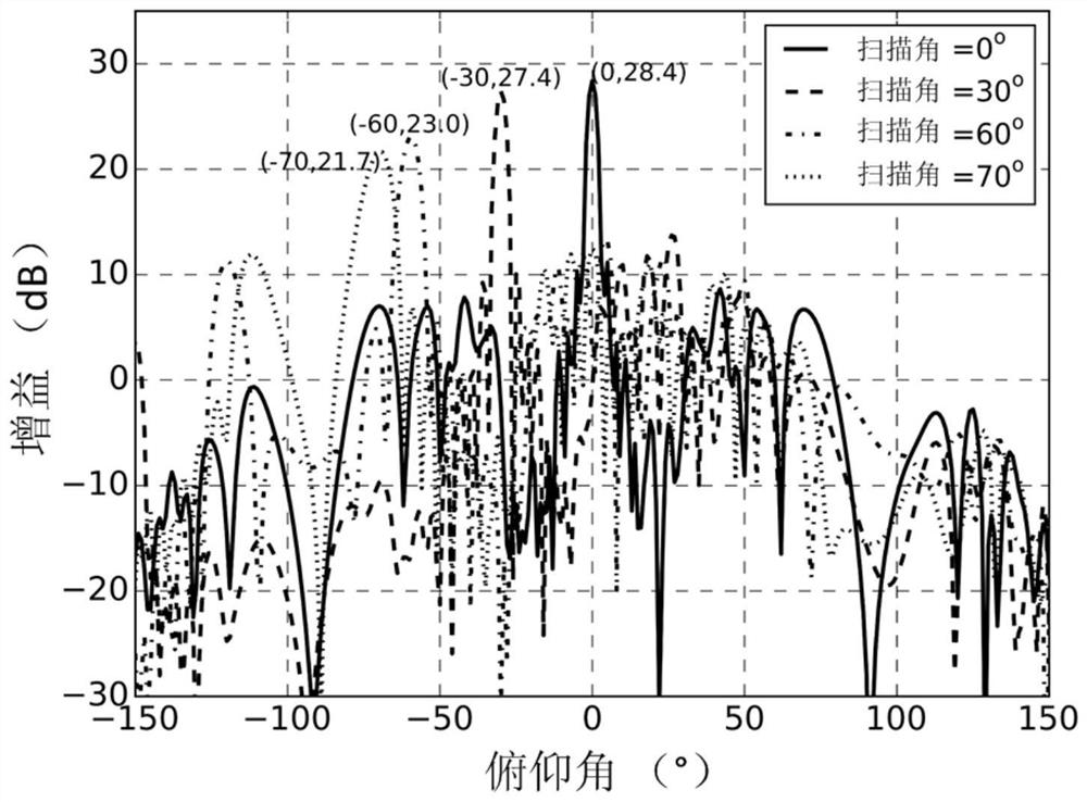
The invention discloses a sparse array method for a large-spacing wide-angle scanning millimeter wave phased-array antenna, and aims to provide a sparse array method which is simple and time-saving, large in unit spacing, macroscopically uniform in grids, low in side lobe, free of grating lobes and high in large-scanning-angle gain. According to the technical scheme, a rectangular coordinate system is constructed with a center of an array as an original point of coordinates, and the coordinate positions of antenna units are calculated according to Fibonacci grids; a helix angle growth coefficient is selected according to a wavelength corresponding to the working frequency of the antenna, and the position coordinates of n antenna units are calculated according to a helix formula with an unit of meter and Fibonacci number; based on the disordered arrangement of the annular sparse array, the number of Fibonacci grid antenna units is set, and the antenna units are aperiodically arranged byusing a Fibonacci spiral curve composition method; and n antenna units are spirally arranged along the Fibonacci to form a non-equidistant involute spiral large-spacing wide-angle scanning millimeterwave phased array which expands outwards at equal intervals according to an arc radius and is gradually far away from a circle center.

Description

technical field [0001] The invention relates to a phased array antenna which is widely used in radar, communication and other fields and has wide-angle scanning capability. Especially for high-density integrated phased array antennas in the communication field, the wide-angle sparse array method with large average spacing and macro-uniform grid. Background technique [0002] Phased array antennas control the amplitude and phase excitation of each radiating antenna element in order to achieve arbitrary beam pointing within the required airspace. The change of the amplitude and phase of the antenna unit needs to be realized by the corresponding transceiver circuit at the back end. Generally, the number of channels of the transceiver circuit is the same as the number of antenna units, so the length and width of the grid area occupied by the transceiver circuit of one channel are usually equal to the antenna cell spacing. [0003] In the field of millimeter-wave communication ...

Claims


Application Information

Patent Timeline
IPC IPC(8): H01Q21/00H01Q3/26
CPCH01Q21/00H01Q3/26
Inventor 温剑姚亚利阳昆侯禄平
Owner 10TH RES INST OF CETC
Learn More