An active clamp no electrolytic capacitor led drive power supply

A technology of LED driving and electrolytic capacitors, which is applied in the direction of electrical components, etc., can solve the problems of large switching stress, switching loss, and high cost, and achieve the effect of realizing no electrolytic capacitors, reducing switching stress, and improving power supply life

Active Publication Date: 2022-08-05
HEBEI UNIV OF TECH
View PDF4 Cites 0 Cited by
  • Summary
  • Abstract
  • Description
  • Claims
  • Application Information

AI Technical Summary

Problems solved by technology

However, due to the existence of the leakage inductance in the flyback converter, there will be resonance between the leakage inductance and the parasitic capacitance of the switch tube, and a voltage spike will appear at both ends of the switch tube, and the switching stress is relatively large, which is unfavorable for device selection
And because the switching tube is a hard switch, there is switching loss, which limits the efficiency of the overall LED drive power supply
[0003] The document with application number 201810788145.0 discloses a bidirectional Cuk circuit-based non-electrolytic capacitor LED drive power supply and its switching method. It uses a bidirectional Cuk structure as a parallel absorption circuit. The Cuk circuit requires two capacitors and inductors. Large, high cost; and the output voltage is reversed, the switching stress of the switch tube of the flyback converter is large, and a high voltage peak will appear at both ends of the switch tube when the switch tube is turned off; and the leakage inductance energy is consumed in the RCD absorption circuit resistors, the leakage inductance energy cannot be utilized
And the working mode of the switching tube is hard switching, so there is switching loss

Method used


Image

  • An active clamp no electrolytic capacitor led drive power supply
  • An active clamp no electrolytic capacitor led drive power supply
  • An active clamp no electrolytic capacitor led drive power supply

Examples


Embodiment Construction

[0029] Specific embodiments of the present invention are given below. The specific embodiments are only used to further illustrate the present invention in detail, and do not limit the protection scope of the claims of the present application.

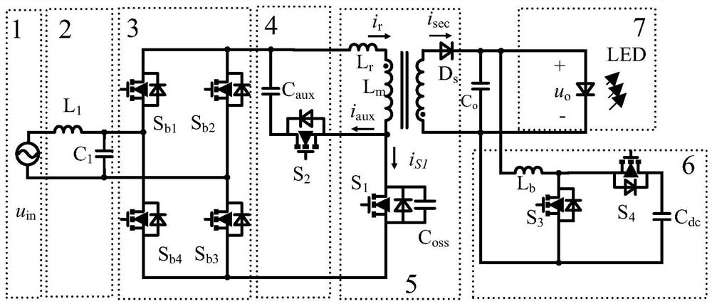
[0030] The present invention provides an active clamping non-electrolytic capacitor LED driving power supply (referred to as driving power supply), which is characterized in that the driving power supply comprises an AC input power supply 1, an input filtering part 2, a rectifying part 3, a clamping circuit 4, a flyback Converter 5, output filter capacitor C o , Parallel absorption circuit 6 and LED load 7;

[0031] The AC input power supply 1 is 220V / 50Hz commercial power.

[0032] The input filtering part 2 adopts LC filtering, and the input filtering inductor L 1 and input filter capacitor C1 The main function of the input filtering part 2 is to filter out the high frequency components of the input.

[0033] The rectifier part 3...


PUM


Abstract

The invention discloses an active clamp non-electrolytic capacitor LED driving power supply, comprising an AC input power supply, an input filter part, a rectifier part, a clamp circuit, a flyback converter, an output filter capacitor Co, a parallel absorption circuit and an LED load; The input filter part is composed of input filter inductor and input filter capacitor; the rectifier part is composed of four switch tubes; the clamping circuit is composed of switch tubes S 2 and the clamping capacitor C aux The flyback converter consists of a flyback transformer, a switch tube S 1 and diode D s Composition; the flyback transformer includes the primary winding and the secondary winding, and the primary winding includes the main inductance L m and leakage inductance L r , the primary winding is connected to the input, and the secondary winding is connected to the output; the parallel absorption loop includes the boost inductor L b , switch tube S 3 , switch tube S 4 and storage capacitor C ds . The present invention introduces an active clamp circuit to reduce the switch tube S 1 switch stress; switch tube S 1 and switch tube S 2 Both realize soft switching, reducing switching loss; at the same time, leakage inductance energy can be fed back.

Description

technical field [0001] The invention belongs to the field of LED lighting driving power supplies, in particular to an LED driving power supply without electrolytic capacitors that applies an active clamping technology to a flyback parallel absorption loop. Background technique [0002] As a new type of light source, LED has shown the incomparable advantages of traditional light sources in terms of life, power consumption, brightness, etc., and is widely used in daily lighting, large-screen display, automobile transportation and other industries. In traditional LED driving power, electrolytic capacitors are used to stabilize the output voltage, but the life of electrolytic capacitors is only 1 / 10 of that of LED light sources, and electrolytic capacitors become the short board of LED driving power. In order to improve the life of the LED driving power supply, it is necessary to remove the electrolytic capacitors in the LED driving power supply. At present, flyback converters ...

Claims


Application Information

Patent Timeline
Patent Type & Authority Patents(China)
IPC IPC(8): H05B45/34H05B45/30
CPCH05B45/34H05B45/30
Inventor 凌跃胜酉家伟李永建田锐
Owner HEBEI UNIV OF TECH
Why Eureka
Try Eureka