
Light-emitting diode lighting equipment power supply for electromagnetic compatibility test

A technology of light-emitting diodes and lighting equipment, applied in the direction of electrical components, etc., can solve the problems of affecting lighting stability, poor consistency of LED lamp bead volt-ampere characteristics, disturbing the power supply of LED lighting equipment, etc., to achieve strong electromagnetic anti-interference ability and long life The effect of long and low ventilation requirements

Pending Publication Date: 2020-11-24
南京容测检测技术有限公司
View PDF8 Cites 0 Cited by
  • Summary
  • Abstract
  • Description
  • Claims
  • Application Information

AI Technical Summary

Problems solved by technology

[0005] Due to the non-linear volt-ampere characteristics of LED lamp beads, the temperature coefficient of volt-ampere characteristics, and poor consistency of lamp bead volt-ampere characteristics, the existing LED lighting equipment usually uses a constant current source for power supply.
Since the constant current source usually uses a switching power supply, it will generate electromagnetic radiation, and the frequency of electromagnetic radiation generated by the lamp will exceed 10kHz, forming electromagnetic interference and affecting the results of the electromagnetic compatibility test
On the other hand, the high-power electromagnetic signal generated during the EMC test will interfere with the normal operation of the power supply, and even cause the protection of the power supply to start, which may also disturb the power supply of LED lighting equipment and affect the stability of lighting.
If you want to solve the electromagnetic compatibility problem of the LED lamp driven by a constant current source, use a shielding device to electromagnetically shield the LED lamp, but because the LED light will generate heat, the light-emitting area cannot be shielded with a conductive material with good light transmission

Method used


Image

  • Light-emitting diode lighting equipment power supply for electromagnetic compatibility test

Examples


Embodiment Construction

[0017] The specific implementation manners of the present invention will be further described below in conjunction with the drawings and examples. The specific embodiments described here are only used to explain the present invention, and the present invention cannot be limited by the specific embodiments.

[0018] The embodiment that the present invention adopts is:

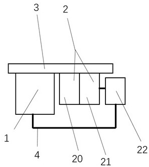
[0019] The power supply for light-emitting diode lighting equipment used for electromagnetic compatibility testing, the power supply includes LED integrated lamp bead 1, linear power supply 2, electromagnetic interference filter 22 and radiator 3; the linear power supply 2 supplies power to the LED integrated lamp bead 1 through the electromagnetic interference filter 22 , so that the LED integrated lamp bead 1 works in a constant voltage state; the LED integrated lamp bead 1 and the linear power supply 2 are close to the radiator 3; the linear power supply 2 includes a transformer 20 and a rectifier 21 .

[00...


PUM


Abstract

The invention discloses a light-emitting diode lighting equipment power supply for an electromagnetic compatibility test. The light-emitting diode lighting equipment power supply mainly comprises an LED integrated lamp bead (1), a linear power supply (2), an electromagnetic interference filter (22) and a radiator (3), wherein the linear power supply (2) supplies power to the LED integrated lamp bead (1) through the electromagnetic interference filter (22), so that the LED integrated lamp bead (1) works in a constant-voltage state; the linear power supply (2) comprises a transformer (20) and arectifier (21); and the rectifier (21) adopts a fast recovery diode, so that harmonic waves generated by the rectification circuit are lower than 1 kHz, and the radiator (3) adopts a natural heat dissipation mode to reduce electromagnetic interference. The lighting equipment is energy-saving and high in illuminance, does not generate electromagnetic interference signals with the frequency of morethan 1 kHz, avoids interference to electromagnetic compatibility test, and has strong electromagnetic anti-interference capability at the same time.

Description

technical field [0001] The invention relates to electromagnetic compatibility testing, in particular to a light-emitting diode lighting equipment power supply for electromagnetic compatibility testing. Background technique [0002] The purpose of electromagnetic compatibility testing is to verify the electromagnetic emission or electromagnetic immunity (sensitivity to external electromagnetic fields) generated by the electrical and electronic products or systems under test (collectively referred to as the test piece). EMC testing is usually carried out in an anechoic chamber, where no external interference can enter the anechoic chamber, nor can there be electromagnetic interference from non-tested parts. [0003] Indoor lighting equipment for EMC testing generally adopts halogen lamps or incandescent lamps without radiation but short life. Since the inside of the anechoic chamber is not allowed to have a large area of ​​electromagnetic wave reflection except the ground, the...

Claims


Application Information

Patent Timeline
Patent Type & Authority Applications(China)
IPC IPC(8): H05B45/36H05B45/3725
CPCH05B45/36H05B45/3725
Inventor 沈学其沈奔杰
Owner 南京容测检测技术有限公司
Learn More