Circuit for driving gate drive transformer

A transformer, pole-driven technology, applied in instruments, electrical components, adjusting electrical variables, etc., can solve problems such as loss, distortion, and PWM duty cycle increase, and achieve the effect of improving efficiency

Inactive Publication Date: 2020-11-27
NINGBO ANXIN CNC TECH
View PDF7 Cites 0 Cited by
  • Summary
  • Abstract
  • Description
  • Claims
  • Application Information

AI Technical Summary

Problems solved by technology

In order to prevent saturation, a capacitor (DC blocking capacitor) is currently used, and it is one of the most common methods to connect the capacitor in series with the primary winding of the gate drive transformer. This capacitor isolates the DC current, and the magnetic core of the gate drive transformer is in the There will be no magnetic flux density saturation in the steady state, but the magnetic core of the gate drive transformer may be saturated in the transient state. At this time, the DC signal of the drive signal will be lost on the secondary winding of the gate drive transformer. , there is a distortion phenomenon, which causes the level of the gate of the switch tube to drop when the PWM duty cycle increases

Method used


Image

  • Circuit for driving gate drive transformer

Examples


Embodiment Construction

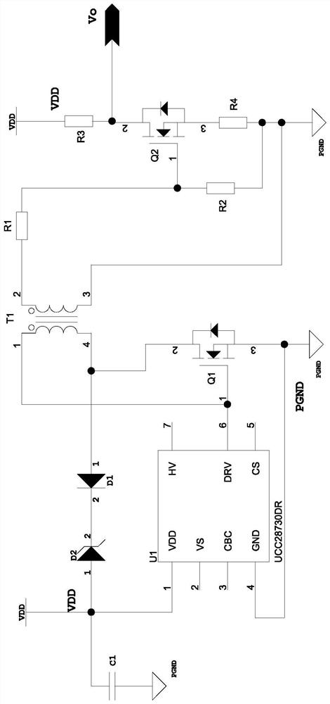
[0012] The present invention will be described in further detail below in conjunction with the embodiments of the drawings.

[0013] The present invention provides a circuit for driving a gate drive transformer, such as figure 1 As shown, it includes a flyback control chip U1, a diode D1, a Zener diode D2, a capacitor C1, and a MOS tube Q1 that can automatically generate a driving signal. The power supply terminal of the flyback control chip U1 is connected to the power supply VDD, and the flyback control chip U1 The power supply terminal of the capacitor C1 is connected to the anode of the Zener diode D2, the cathode of the Zener diode D2 is connected to the cathode of the diode D1, the anode of the diode D1 is connected to the drain of the MOS transistor Q1, and its common connection is connected to The synonymous end of the primary winding of the gate drive transformer T1 is connected, the gate of the MOS transistor Q1 is connected to the drive signal output end of the flyback...


PUM


Abstract

The invention discloses a circuit for driving a gate drive transformer. The circuit comprises a flyback control chip, a diode, a voltage stabilizing diode, a capacitor, and a triode or an MOS tube. The power supply end of the flyback control chip is connected with a power supply; the power supply end of the flyback control chip is respectively connected with one end of the capacitor and the anodeof the voltage stabilizing diode; the cathode of the voltage stabilizing diode is connected with the cathode of the diode; the anode of the diode is connected with the collector of the triode or the drain of the MOS tube; the common connection end of the diode is connected with the synonym end of the primary winding of a gate drive transformer; the base electrode of the triode or the grid electrode of the MOS tube is connected with the driving signal output end of the flyback control chip; the common connecting end of the triode or the grid electrode of the MOS tube is connected with the dotted terminal of the primary winding of the grid driving transformer; and the emitting electrode of the triode or the source electrode of the MOS tube, the grounding end of the flyback control chip and the other end of the capacitor are all grounded. The grid driving transformer has the advantage that the phenomenon of magnetic flux density saturation of the magnetic core of the grid driving transformer in a transient state is avoided.

Description

Technical field [0001] The present invention relates to a gate drive transformer, in particular to a circuit for driving the gate drive transformer. Background technique [0002] In the industrial control industry, switching power supplies are widely used, especially flyback switching power supplies are widely used. Flyback switching power supplies include single-tube flyback switching power supplies and dual-tube flyback switching power supplies. Among them, dual-tube flyback switching power supplies are often used to improve the efficiency of low-power isolated converters. Compared with the single-tube flyback switching power supply, the dual-tube flyback switching power supply requires a floating high-side drive. In the dual-tube flyback switching power supply, the gate of the switching tube is driven by the high level of the gate drive transformer, and the gate drive requires a certain method. If the magnetic core of the gate drive transformer is not in each cycle If it is ...

Claims


Application Information

Patent Timeline
Patent Type & Authority Applications(China)
IPC IPC(8): H02M1/08H02M3/335
CPCH02M1/08H02M3/33576H02M1/0054Y02B70/10
Inventor 袁世博陈振宇章江锋虞乾恒朱钜録张晓峰谢子方林中轩陈赛虎周兵兵
Owner NINGBO ANXIN CNC TECH
Why Eureka
Try Eureka