
Shaft mill

A mill and shaft grinding technology, which is applied in the fields of smoke removal, pollution prevention, grain processing, etc., can solve the problems of secondary pollution, machine damage, increased wear of the body and liner, etc.

Pending Publication Date: 2020-12-01
武思军
View PDF0 Cites 3 Cited by
  • Summary
  • Abstract
  • Description
  • Claims
  • Application Information

AI Technical Summary

Problems solved by technology

During the use of the vertical mill roller body and the wear-resistant liner, once there is a fit gap, the wear between the body and the liner will be aggravated, and the hot air and cement particles will continuously scour the mating surface, resulting in grooves. Causes impact and collision between the body and the liner. In severe cases, the liner cracks or even breaks, and the machine is damaged, especially the damage of the reducer, resulting in a vicious incident.
Once such problems occur, the general repair method is difficult to solve, and the replacement cost is high; the assembly requirements of vertical mill roller bearings are relatively strict, and enterprises generally adopt the method of cooling the bearings in dry ice.
[0007] As the quality requirements of powder products in today's market continue to refine, foreign advanced companies have a powder pass rate of more than 90% in terms of grinding mesh requirements, while the actual pass rate of powder companies in my country is less than 8%. 10. It not only affects the beneficiation effect, but also reduces the quality requirements of mineral products
[0008] It has always been a technical problem in this field to remove iron from non-metallic minerals such as kaolin, potassium feldspar, quartz sand, magnesia, and alumina, especially kaolin. A very small amount of iron oxide impurities will greatly reduce the quality of kaolin. However, during the grinding production process of ball mills and other grinding equipment, some iron scraps, iron powders and other iron impurities will be produced, causing secondary pollution, which is not conducive to the improvement of the quality of such minerals

Method used


Image

  • Shaft mill
  • Shaft mill
  • Shaft mill

Examples


Embodiment Construction

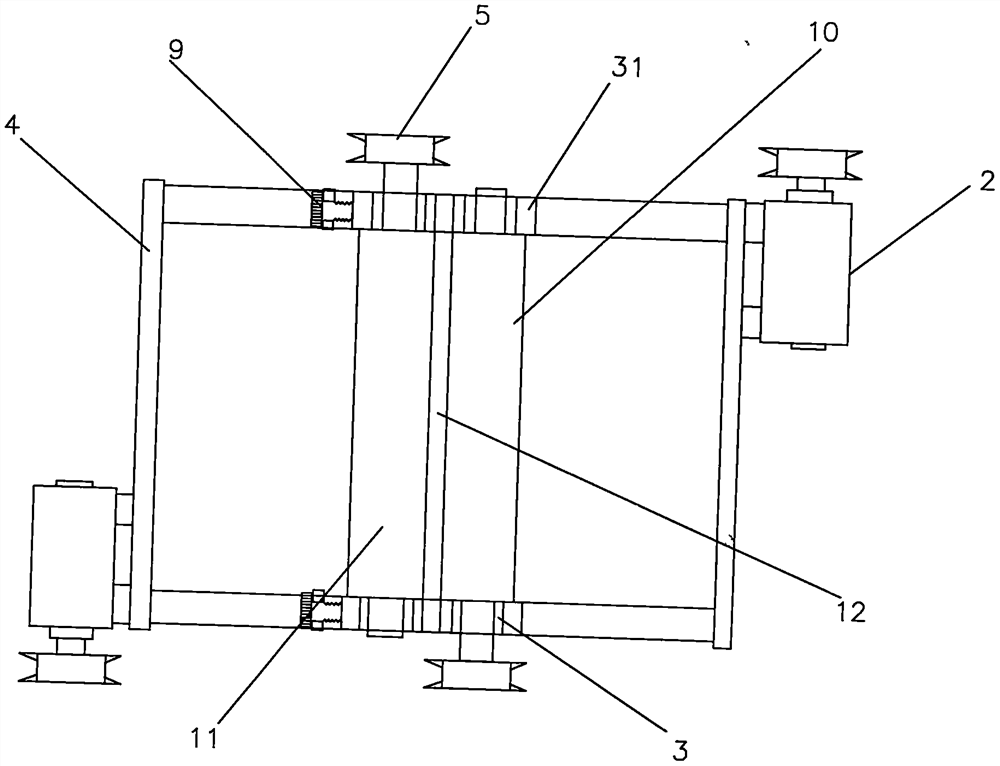
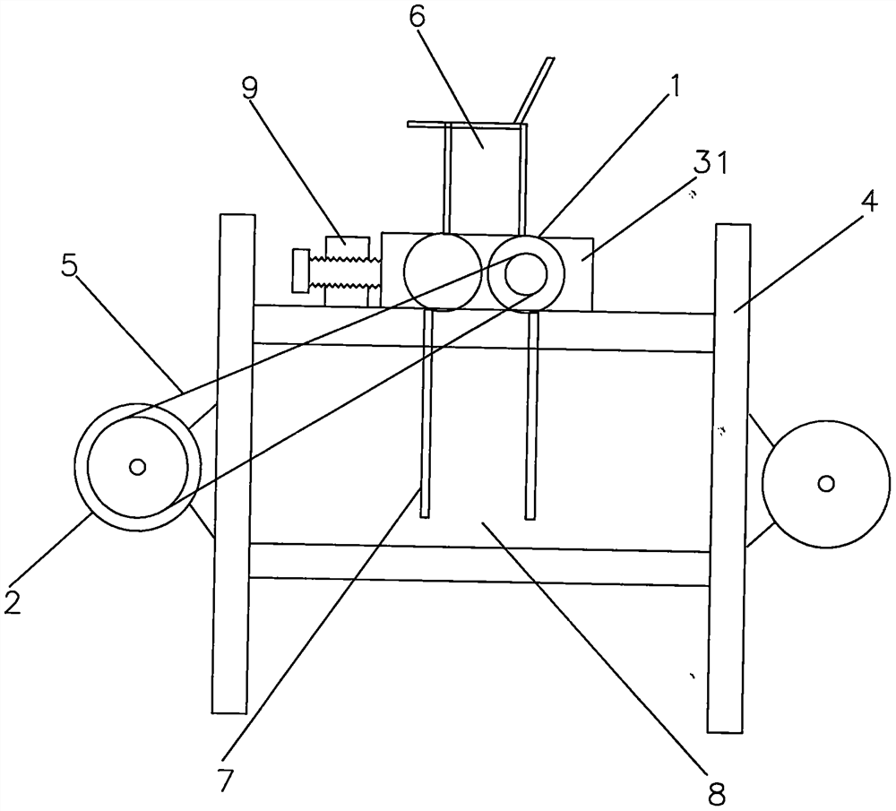
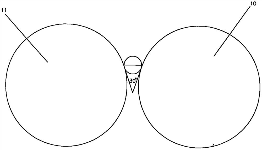
[0045] Implementation column 1, such as figure 1 , figure 2 , image 3 , Figure 4 , Figure 5 with Image 6 As shown in the figure: a shaft mill is in the shape of a cabinet and generally has four legs. The frame 4 of the mill is wrapped with a shell to form a cabinet shape. The frame 4 uses several thick square steel beams or steel plates to make a combined frame. Generally, four square steel beams with relatively thick dimensions are used as vertical columns, and the four columns are separated by a certain distance, and are fastened and connected with horizontal square steel beams and vertical square steel beams. The beam and the longitudinal square beam steel are the beam and the longitudinal beam of the frame 4. The beam is generally a double-beam structure, and a pair of square steels are arranged side by side with a certain gap to form the beam. The gap can be used for the bearing holder 31 of the movable grinding shaft 11 as a horizontal Easy to move and fasten w...


PUM


Abstract

The invention discloses a shaft mill, and relates to ore grinding equipment to solve the problems that an existing ore mill is extremely low in powder grinding efficiency and extremely large in energyconsumption. Double-mill shafts rotating at a relatively-high speed are used for punching ores to crush the ores. According to the technical principle, the shaft mill comprises components of the double-mill shafts, a motor, a bearing, a rack and the like, two grinding shafts which rotate at a relatively-high speed are adopted as grinding pieces, and the two grinding shafts are spaced by a certaincrack according to the powder grinding requirement of the ores; the multiple double-mill shafts are horizontally arranged in the rack from top to bottom in sequence; the width of the crack of the double grinding shafts is determined according to ore grinding requirement; and the ores are sequentially arranged according to the requirements that coarse materials are located above, and fine materials are located below, the ores are crushed under punching of the double-mill shafts rotating at the relatively-high speed, the crushed fine particles directly fall and are not continuously pressed andground any more, electric energy waste caused by repeated pressing and grinding is avoided, the two grinding shafts rotating relatively do not make contact, impact abrasion between the grinding piecesis avoided, and scrap iron is not generated in the ore grinding process. The powder passing rate after ore grinding reaches 100%.

Description

technical field [0001] The invention relates to a kind of ore grinding equipment, especially the ore mill which utilizes relatively rotating double grinding shafts to generate punching force. It is mainly used for fine grinding and superfine grinding of various ore powders, and can also be used for grain flour processing. . Background technique [0002] my country's coal mines, iron ores, cement and other ores are mined with billions of tons every year. Most of these ores need to be finely ground before they can be properly sorted and applied. Existing various types of grinding machines The efficiency is extremely low, and the energy consumption is huge. According to data analysis, the grinding efficiency of the mill is only about 1%, and most of the electric energy is consumed as heat energy. Among the existing grinding equipment, the ball mill is the most widely used. It accounts for more than 80%. These grinding equipment are extremely power-hungry. Taking a ball mill wit...

Claims


Application Information

Patent Timeline
IPC IPC(8): B02C4/02B02C4/30B02C4/32B02C4/42B02C23/08B02C23/02B02C4/28B08B17/02B08B15/04
CPCB02C4/02B02C4/28B02C4/286B02C4/30B02C4/32B02C4/42B02C23/08B08B15/04B08B17/02
Inventor 武思军
Owner 武思军
Learn More