Pneumatic micro-drill driving device with air cooling function

A driving device and functional technology, applied in feeding devices, manufacturing tools, boring/drilling, etc., can solve the problems of large space occupation, wear of the cutter head, and reduced strength, so as to improve operating efficiency, reduce space occupation, and operate The effect of space enhancement

Pending Publication Date: 2020-12-01
HUBEI UNIV OF SCI & TECH
View PDF0 Cites 0 Cited by
  • Summary
  • Abstract
  • Description
  • Claims
  • Application Information

AI Technical Summary

Problems solved by technology

[0003] Specifically, the refinement of the drill bit reduces its strength, and problems such as breakage, damage, and deformation seriously affect the service life of the drill bit; the traditional drill bit drive mechanism is an integration of multiple control mechanisms, which is suitable for automated production. It takes up a lot of space, and generally includes a rotary drive unit that drives the micro-drill to rotate and a knife-feed drive unit that controls the longitudinal feed / exit of the micro-drill. In the automated production process, it is not only necessary to coordinate the two drive units, but also to reduce the Due to the impact force of the drill bit, the drill bit always maintains a certain rotation speed, and the continuous processing of the PCB board is realized through the longitudinal reciprocating motion and the translation and switching of the PCB board. The drill bit is always in a state of high heat and high intensity, which has a great impact on the service life of the drill bit
[0004] In addition, during the processing, whether it is entering or exiting the tool, the drill directly contacts the PCB board at a relatively constant high speed (neglecting the change of the speed when it is in contact with the board, it can be assumed that its speed is constant). The method causes the following problems: 1), the instantaneous cutting heat will cause local thermal deformation to the PCB processing part; 2), the greater impact force will lead to the increase of PCB positioning difficulty and the positioning strength of PCB board (especially the micro PCB board during the processing process is not enough) 3) There is no longitudinal buffer between the PCB board and the drill bit, which causes high-strength "cutting" of the PCB board, which makes the PCB board hole or slot edge burrs / burrs larger, usually requiring two Repairing and deburring once in a while has a negative impact on processing efficiency, processing accuracy and processing quality; 4) In the initial stage of tool feeding, since the micro-drill has not yet achieved "eat silk" with the plate, the resistance at the end of the micro-drill makes the coaxiality Negatively affected, it is easy to cause severe wear, edge chipping and knife breakage of the cutter head. Due to the existence of the rake angle, rear angle, front angle and helix angle of the micro-drill, the micro-drill is subject to greater stress off the axis, and it is easy to The deformation of the mid-section of the micro-drill will greatly affect the service life and processing accuracy of the micro-drill after the coaxiality is affected
[0005] Heat dissipation is also an important factor to prolong the service life of micro-drills. The existing equipment that drives the rotation of micro-drills does not have the means to effectively dissipate heat from micro-drills

Method used


Image

  • Pneumatic micro-drill driving device with air cooling function
  • Pneumatic micro-drill driving device with air cooling function
  • Pneumatic micro-drill driving device with air cooling function

Examples


Embodiment Construction

[0035] The following are specific embodiments of the present invention and in conjunction with the accompanying drawings, the technical solutions of the present invention are further described, but the present invention is not limited to these embodiments.

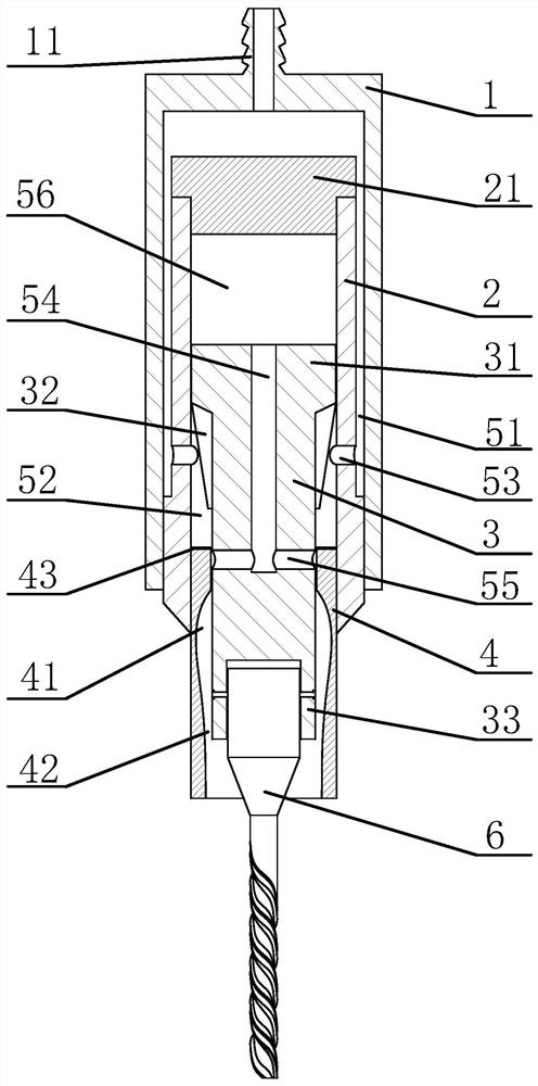
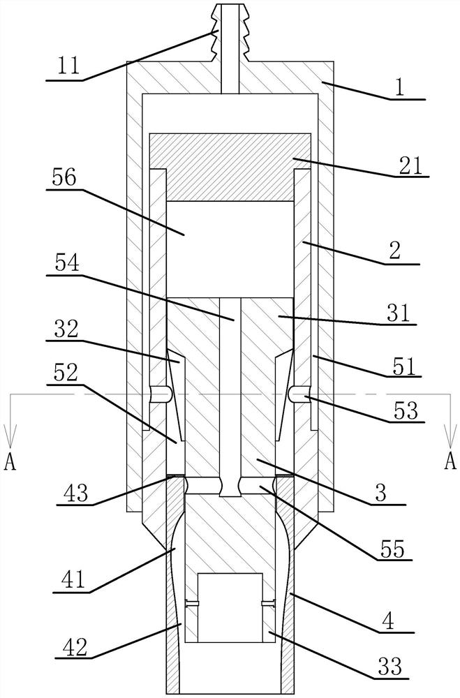
[0036] Such as figure 1 with figure 2 As shown, the drive head includes a housing 1, a middle sleeve 2, a plunger 3 and a high-pressure air source, the middle sleeve 2 is fixed in the housing 1, and an air inlet passage 51 is formed between the outer wall of the middle sleeve 2 and the inner wall of the housing 1 The upper end of the plunger 3 has a piston 31 that is rotatably connected to the inner wall of the middle sleeve 2, the middle part of the plunger 3 has an impeller 32, and an adjustment sleeve 4 is connected between the lower end of the plunger 3 and the middle sleeve 2. The adjustment sleeve 4 is threadedly connected with the middle sleeve 2, and the adjustment sleeve 4 is slidingly connected with the plunger...


PUM


Abstract

The invention provides a pneumatic micro-drill driving device with an air cooling function, and belongs to the technical field of precision machinery. The device comprises a shell, a middle sleeve anda plunger, wherein the middle sleeve is fixed in the shell, an air inlet channel is formed between the middle sleeve and the shell, the upper end of the plunger is provided with a piston rotatably connected to the inner wall of the middle sleeve, the middle of the plunger is provided with an impeller, an adjusting sleeve is connected between the lower end of the plunger and the middle sleeve, andthe middle of the plunger is provided with a plurality of functional holes communicated with an airflow back-and-forth channel; and the lower end of the plunger is provided with a micro-drill mounting head, a flow guide cavity is formed between the inner wall of the lower end of the adjusting sleeve and the outer wall of the lower end of the plunger, an annular overflow channel is formed betweenthe lower end of the flow guide cavity and the outer wall of the plunger, and the flow guide cavity is an annular cavity with the hole diameter gradually decreased from top to bottom. The device has the advantages of high operation efficiency and the like.

Description

technical field [0001] The invention belongs to the technical field of precision machinery, and relates to a pneumatic micro-drill driving device with an air-cooling function. Background technique [0002] PCB board is also known as printed circuit board and printed circuit board. It is an important electronic component, and it is also the support body of electronic components and the carrier of electrical connection. Due to the small size, thinness, and precision, the drill bits such as micro screwdrivers and milling cutters used for drilling and milling are also becoming more refined, and the requirements for the driving mechanism that controls the rotation and expansion of the drill bit are also getting higher and higher. [0003] Specifically, the refinement of the drill bit reduces its strength, and problems such as breakage, damage, and deformation seriously affect the service life of the drill bit; the traditional drill bit drive mechanism is an integration of multipl...

Claims


Application Information

Patent Timeline
Patent Type & Authority Applications(China)
IPC IPC(8): B23B41/00B23B47/22B23Q11/10B23Q11/00
CPCB23B41/00B23Q5/22B23Q11/0042B23Q11/10
Inventor 王波
Owner HUBEI UNIV OF SCI & TECH
Why Eureka
Try Eureka