Pre-treatment equipment and treatment method for concrete prefabricated part production
A concrete prefabricated part and pretreatment technology, which is applied in the direction of pretreatment surface, metal processing equipment, grinding/polishing equipment, etc., can solve the problems of manual operation, low efficiency, and large manpower consumption for grinding and cleaning
- Summary
- Abstract
- Description
- Claims
- Application Information
AI Technical Summary
Problems solved by technology
Method used
Image
Examples
Embodiment 1
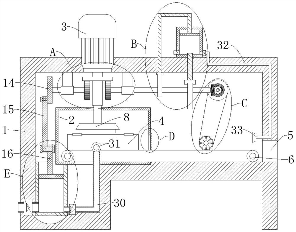
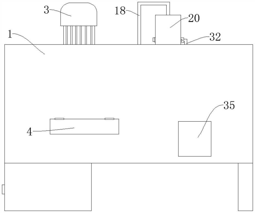
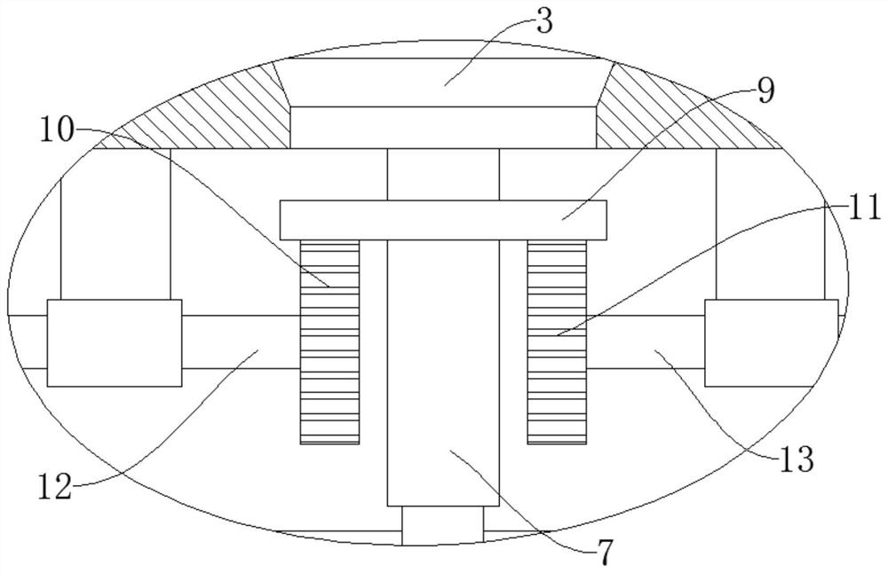
[0037] refer to Figure 1-7, a kind of concrete prefabricated part production pretreatment equipment and treatment method, comprise box body 1, box door 4, conveyer belt 6, it is characterized in that, box door 4 is rotatably connected to the side wall of box body 1, and conveyor belt 6 is positioned in box body 1 , the box body 1 is provided with a cleaning chamber 2, the side wall of the cleaning room 2 is rotatably connected with a baffle plate 27, the side wall of the box body 1 is provided with a discharge port 5, and the box body 1 is provided with a first gas cylinder 28, and the box body 1 is provided with a motor 3, the output end of the motor 3 is fixedly connected with a gear plate 9, the lower end of the gear plate 9 is fixedly connected with an electric telescopic rod 7, and the telescopic end of the electric telescopic rod 7 is fixedly connected with a grinding disc 8, and the box body 1 is fixed Two sets of fixed rods are connected, the fixed rods are located on...
Embodiment 2
[0040] refer to Figure 1-7 , a kind of concrete prefabricated part production pre-treatment equipment and treatment method, basically the same as embodiment 1, further, the second air cylinder 20 is fixedly connected on the box body 1, and the second rotating shaft 13 is fixedly connected on the other fixed rod One end of the second rotating shaft 13 close to the gear plate 9 is fixedly connected with the second gear 11, the second gear 11 meshes with the gear plate 9, and the second rotating shaft 13 is fixedly connected with the first cam 17 in sequence in the direction away from the second gear 11 and the second cam 21, the first cam 17 is slidably connected with the second push rod 18, the end of the second push rod 18 away from the first cam 17 is fixedly connected with the second piston 19, and the second piston 19 is slidably connected to the second cylinder 20, the lower end of the second gas cylinder 20 is provided with an air intake pipe, the lower end of the second...
Embodiment 3
[0042] refer to Figure 1-7 , a kind of concrete prefabricated parts production pretreatment equipment and treatment method, and embodiment 1 is basically the same, further is, the end of the second rotating shaft 13 away from the second gear 11 is fixedly connected with a bevel gear 24, and the inside of the box 1 is rotatably connected There is a rotating shaft 23, and the rotating shaft 23 is meshed with the bevel gear 24. The oiling roller 25 is connected to the box body 1 in rotation. The oiling roller 25 is a hollow structure, and the side wall of the oiling roller 25 is provided with an oil discharge hole. One end of the oiling roller 25 is connected with an oil tank 35, and the oil tank 35 is arranged on the side wall of the box body 1. The oiling roller 25 is connected with the rotating shaft member 23 through a transmission belt 26, and the bevel gear 24 rotates with the second rotating shaft 13 and drives the rotating shaft member 23 rotates, and the rotating shaft ...
PUM
 Abstract
Description
Claims
Application Information
 - R&D
- Intellectual Property
- Life Sciences
- Materials
- Tech Scout
- Unparalleled Data Quality
- Higher Quality Content
- 60% Fewer Hallucinations
Browse by: Latest US Patents, China's latest patents, Technical Efficacy Thesaurus, Application Domain, Technology Topic, Popular Technical Reports.
© 2025 PatSnap. All rights reserved.Legal|Privacy policy|Modern Slavery Act Transparency Statement|Sitemap|About US| Contact US: help@patsnap.com


