Power take-off control system, method and device, electronic equipment and storage medium

A technology of a control system and a control method, which is applied in the directions of control devices, fluid pressure actuation devices, fluid pressure actuation system components, etc., can solve the problems of shortening battery life, low battery power utilization, and increasing use costs.

Active Publication Date: 2020-12-01
HUNAN SANY MEDIUM TONNAGE HOISTING MASCH CO LTD
View PDF12 Cites 1 Cited by
  • Summary
  • Abstract
  • Description
  • Claims
  • Application Information

AI Technical Summary

Problems solved by technology

[0005] The purpose of the embodiment of the present application is to provide a power take-off control system, method, device, electronic equipment and storage medium, which ensures the energy supply of the crane’s upper loading action through the energy storage device, and the motor only needs to be started during the upper loading ac

Method used


Image

  • Power take-off control system, method and device, electronic equipment and storage medium
  • Power take-off control system, method and device, electronic equipment and storage medium
  • Power take-off control system, method and device, electronic equipment and storage medium

Examples


Embodiment 1

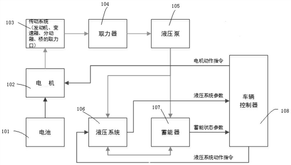
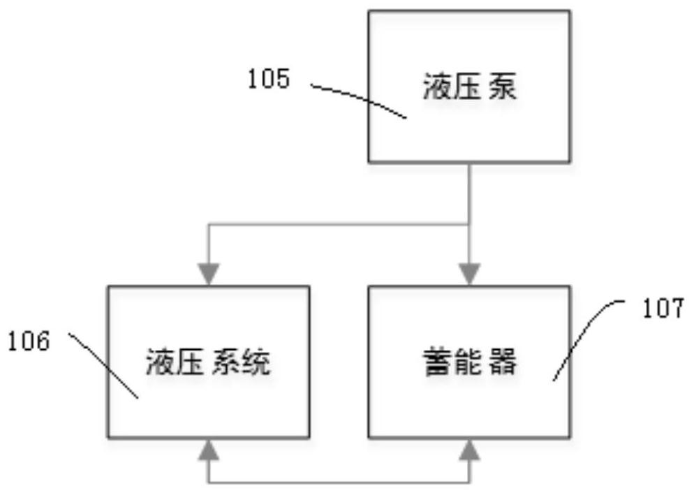
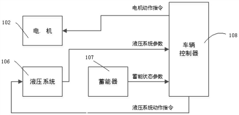
[0067] Please see figure 1 , figure 1 It is a structural block diagram of a power take-off control system provided in the embodiment of this application. This system can be applied to the power take-off control of a crane. The system specifically includes a motor 102, a hydraulic pump 105, a hydraulic system 106, an energy storage device, and a vehicle controller 108. The specific connections are as follows:

[0068] The battery 101 is electrically connected to the motor 102 through a power circuit, and is used to provide energy to the motor 102; the input end of the transmission system 103 is connected to the motor 102, and the output end of the transmission system 103 is connected to the input end of the power take-off 104. The output end of the device 104 is connected to the hydraulic pump 105 in transmission, and the hydraulic pump 105 is connected to the hydraulic system 106 through a hydraulic oil circuit, so that the motor 102 provides energy to the hydraulic system 10...

Embodiment 2

[0077] The embodiment of this application provides a power take-off control method, which is applied to the vehicle controller 108 in Embodiment 1, such as Figure 4 As shown, it is a flow chart of the power take-off control method, and the method may specifically include the following steps:

[0078] Step S100: Receive a power take-off state feedback signal to determine whether it is in a power take-off state;

[0079] The power take-off status feedback signal is used to reflect whether it is in the power take-off state, and the opening and closing of the power take-off state can also be controlled through the opening and closing of the switch valve.

[0080] Step S200: If yes, receive the working state parameters of the hydraulic system 106;

[0081] Step S300: judging whether the hydraulic system 106 is in a working state according to working state parameters;

[0082] In the power take-off state, the working state parameters of the hydraulic system 106 are received. The ...

Embodiment 3

[0102] The embodiment of this application provides a power take-off control device, which is applied to the vehicle controller 108 in Embodiment 2, such as Figure 7 Shown is the structural block diagram of the power take-off control device, which includes:

[0103] The signal receiving module 100 is used to receive the power take-off state feedback signal to determine whether it is in the power take-off state;

[0104]The parameter receiving module 200 of the hydraulic system 106 is configured to receive the working state parameters of the hydraulic system 106 if it is in the power take-off state;

[0105] A working state judging module 300, configured to judge whether the hydraulic system 106 is in a working state according to the working state parameters;

[0106] An action command sending module 400, configured to send the motor 102 an action command to the motor 102 if the hydraulic system 106 is in a working state;

[0107] A first energy judging module 500, configured...


PUM


Abstract

The embodiments of the invention provide a power take-off control system, method and device, electronic equipment and a storage medium, and relates to the technical field of vehicle manufacturing. Thepower take-off control system comprises an energy storage device which is correspondingly connected with a hydraulic system and a hydraulic pump through hydraulic oil ways and used for exchanging energy with the hydraulic system and the hydraulic pump; and a controller is correspondingly connected with a motor, the hydraulic system and the energy storage device through a control circuit and usedfor receiving working state parameters of the hydraulic system and the energy storage device and controlling the motor and the hydraulic system to act. Through energy supply of the energy storage device, energy supply of loading action of a crane is guaranteed, the motor only needs to be started during loading action without being in a working state for a long time, the electric energy is saved, and the problems that the electric energy utilization rate of a battery is low, the service life of the battery is shortened, and the use cost is greatly increased due to the fact that the motor of anexisting electric crane is in the working state for a long time are solved.

Description

technical field [0001] The present application relates to the technical field of vehicle manufacturing, and in particular, to a power take-off control system, method, device, electronic equipment, and storage medium. Background technique [0002] When the power take-off operation of the existing electric vehicle crane is performed by the power take-off system, the motor needs to continue to work to provide power for the hydraulic system. , the motor runs at a fixed speed (idle speed) in order to provide hydraulic energy for the hydraulic system to build pressure in time. [0003] The characteristics of the existing electric cranes are that the power battery is expensive and the loading capacity of the battery is limited, and the limited battery capacity must also take into account the mileage and working time of the crane. In addition, the operating conditions of the electric crane are basically low frequency. The job interval time is greater than the job time. [0004] Ba...

Claims


Application Information

Patent Timeline
IPC IPC(8): B66C13/20F15B1/02F15B21/14B60K25/06
CPCB66C13/20F15B1/024F15B21/14B60K25/06F15B2211/212F15B2211/205B60K2025/065
Inventor 朱林高浩向纯
Owner HUNAN SANY MEDIUM TONNAGE HOISTING MASCH CO LTD
Why Eureka
Try Eureka