Eureka AIR delivers breakthrough ideas for toughest innovation challenges, trusted by R&D personnel around the world.

Hose suction device used for grain collection

A material suction device and hose technology, applied in the field of food processing, can solve the problems of inability to distinguish impurities, existence of impurities, adsorption to the inside of the body, etc., to achieve the effect of ensuring the quality of food

Inactive Publication Date: 2020-12-08
杨松柏
View PDF8 Cites 2 Cited by
  • Summary
  • Abstract
  • Description
  • Claims
  • Application Information

AI Technical Summary

Problems solved by technology

[0004] The invention provides a hose suction device for grain collection, which has the advantages of being convenient to absorb the fine dust in the grain, ensuring the quality of the grain, and maintaining the air quality in the grain suction area, which solves the problem of the existing When the hose suction device is collecting grain, one end of the suction pipe is placed on the ground, and the other end of the material is placed on the collecting cart, so that the grain on the ground after drying can be sucked into the grain cart. When the absorbed grain is released, since the inhaled grain (referring to small particles such as wheat and corn) is released downward by its own gravity, when the grain is released into the car, it is convenient to scatter the dust attached to the surface of the grain in the air, because Dust carries many bacteria, viruses and insect eggs. When it floats in the air, it is easy to absorb the surrounding people into the body, induce human respiratory diseases, and endanger human health. Excessive dust will also cause environmental pollution. , affect people's normal life and work, and when the grain contains relatively heavy dust particles, the existing hose suction device cannot distinguish the impurities in time, resulting in the presence of impurities in the collected grain, which affects the collected grain. overall food quality

Method used


Image

  • Hose suction device used for grain collection
  • Hose suction device used for grain collection
  • Hose suction device used for grain collection

Examples


Embodiment Construction

[0019] The following will clearly and completely describe the technical solutions in the embodiments of the present invention with reference to the accompanying drawings in the embodiments of the present invention. Obviously, the described embodiments are only some, not all, embodiments of the present invention. Based on the embodiments of the present invention, all other embodiments obtained by persons of ordinary skill in the art without making creative efforts belong to the protection scope of the present invention.

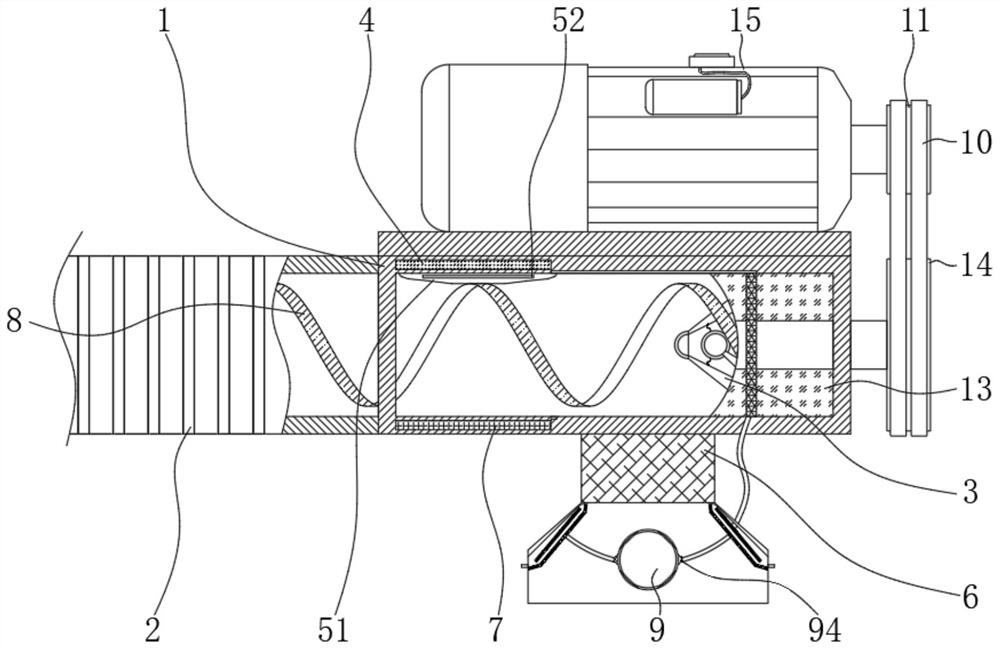
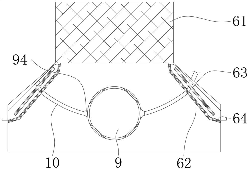
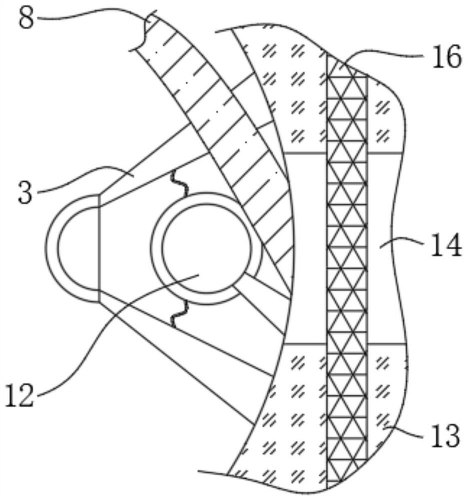
[0020] see Figure 1-5 , a hose suction device for grain collection, comprising a suction body 1, a feed hose 2 is fixedly sleeved on the left side of the suction body 1, and the top of the suction body 1 is fixedly installed There is a servo motor 15, the output shaft of the servo motor 15 is fixedly sleeved with a drive wheel 11, the right side of the inner cavity of the suction body 1 is fixedly connected with a filling pad 13, and the left side of the fill...


PUM


Abstract

The invention relates to the technical field of grain processing, and discloses a hose suction device used for grain collection. The hose suction device comprises a suction machine body, the left sideof the suction machine body is fixedly sleeved with a feeding hose, and the top of the suction machine body is fixedly provided with a servo motor. According to the hose suction used for grain collection, through cooperation of a strip-shaped magnetic plate, a linkage device, a discharging and dust removal device, a permanent magnet piece and the servo motor, a guide connection column in the linkage device is driven to cut a magnetic field line formed between the strip-shaped magnetic plate and the permanent magnet piece, induction current is generated, and kinetic energy of the linkage device is conveniently converted into electric energy; the generated electric energy is transmitted to an electrostatic plate through an annular guide pad and a fixedly connected cable, so that dust is combined with negative ions in air, the dust is promoted to float to the surface of an anode of the annular guide pad, adsorbing is conveniently carried out on fine dust in grain, the air quality of a grain suction area is kept while the grain quality is guaranteed; and the health of a human body is protected.

Description

technical field [0001] The invention relates to the technical field of grain processing, in particular to a hose suction device for grain collection. Background technique [0002] The hose suction device drives the auger to rotate through the motor shaft through the linkage rod or the conveyor belt. When the motor is started, the motor drives the auger to rotate, and the grain at the collecting port will be released under the action of the rotating spring. It is a device that unloads through the discharge port under the action of the gravity of the grain itself when it rises in the direction of the helix angle of the spring and reaches the corresponding target point. [0003] When the existing hose suction device is collecting grain, one end of the suction pipe is placed on the ground, and one end of the material discharge is located on the collecting cart, so that the grain on the ground after being dried can be sucked into the grain cart. When the absorbed grain is releas...

Claims


Application Information

Patent Timeline
Patent Type & Authority Applications(China)
IPC IPC(8): B65G65/28B65G53/24B65G53/48B65G69/18B65G69/12
CPCB65G53/24B65G53/48B65G65/28B65G69/12B65G69/185B65G2201/04
Inventor 杨松柏
Owner 杨松柏
Why Eureka
Eureka Blog
Learn More