Continuous feeding and discharging sintering rotary furnace

A rotary furnace, charging and discharging technology, applied in rotary drum furnaces, furnaces, charge and other directions, can solve the problems of increased operating costs, inability to accurately control material residence time, and many influencing factors, and achieve precise control of sintering time and accurate sintering time. Controllable, large water-cooled contact area

Pending Publication Date: 2020-12-08
48TH RES INST OF CHINA ELECTRONICS TECH GROUP CORP +1
View PDF4 Cites 2 Cited by
  • Summary
  • Abstract
  • Description
  • Claims
  • Application Information

AI Technical Summary

Problems solved by technology

[0003] In order to solve the above problems, the current existing solutions are as follows: when the material is agglomerated, it is manually crushed in advance or an additional crushing device is added. These two forms lead to the inability to realize continuous production of continuous equipment or the need to add additional series devices to increase operating costs.
When solving the situation of high moisture content or large sintering oxygen consumption, the existing method is to add a lifting plate, but it is difficult to achieve precise control of the sintering residence time. Angle of repose), resulting in the inability to accurately control the residence time of the material
When realizing the precise control of sintering residence time, the existing equipment is controlled by adding a screw pusher device. The diameter of the air flow channel is reduced, and the air flow rate is reduced under the same flow rate, thereby weakening the drying or oxidation effect
In the cooling setting, the existing equipment uses the outer wall of the furnace tube to spray cooling water, which has low cooling efficiency and large water consumption

Method used


Image

  • Continuous feeding and discharging sintering rotary furnace
  • Continuous feeding and discharging sintering rotary furnace

Examples


Embodiment Construction

[0025] The present invention will be described in further detail below in conjunction with the accompanying drawings and specific embodiments.

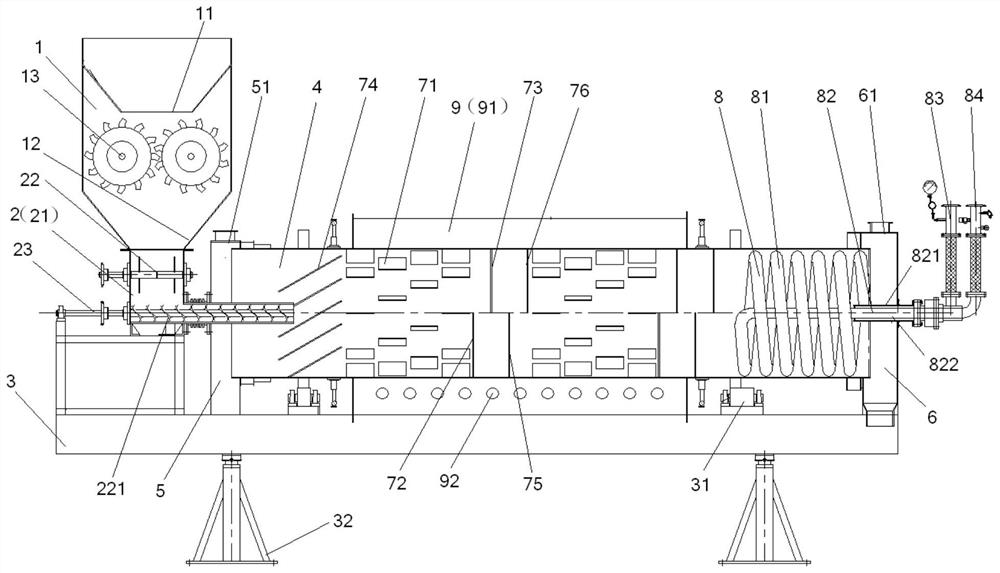
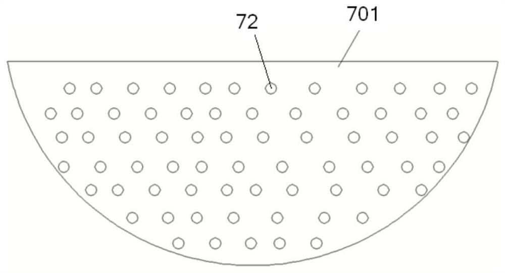
[0026] Such as figure 1 and figure 2 As shown, the continuous feeding and discharging sintering rotary furnace of this embodiment includes a feed bin 1, a feeder 2, a main frame 3, a furnace tube 4, a furnace head cover 5 and a furnace tail cover 6, and the furnace tube 4 is supported on the main frame 3, the furnace head cover 5 and the furnace tail cover 6 are respectively provided with the head end and the tail end of the furnace tube 4, and the feeder 2 is arranged at the furnace head of the furnace tube 4 and passes through the furnace head cover 5 to connect with the furnace tube 4, and then The silo 1 is provided with a primary hopper 11 and a secondary hopper 12, and a crushing pair of rollers 13 is arranged between the primary hopper 11 and the secondary hopper 12. The outlet of the primary hopper 11 is connected to the cru...


PUM


Abstract

The invention discloses a continuous feeding and discharging sintering rotary furnace. The continuous feeding and discharging sintering rotary furnace comprises a feeding bin, a feeder, a main frame,a furnace tube, a furnace head cover and a furnace tail cover, wherein the furnace tube is supported on the main frame; the furnace head cover and the furnace tail cover are arranged at the head end and the tail end of the furnace tube correspondingly; the feeder is arranged at a furnace head of the furnace tube and penetrates the furnace head cover to be in butt joint with the furnace tube; a first-level hopper and a second-level hopper are arranged in the feeding bin; a crushing roller couple is arranged between the first-level hopper and the second-level hopper; an outlet of the second-level hopper is in butt joint with the feeder; at least one material raising area and at least one material blocking area are arranged in the furnace tube and are alternately arranged at intervals in theaxial direction; each material raising area is provided with a plurality of circles of material raising plates, and each circle of material raising plates are provided with the multiple material raising plates arranged at intervals in the circumferential direction; and each material blocking area is provided with a first material blocking plate and a second material blocking plate, wherein the first material blocking plate and the second material blocking plate are oppositely arranged on the inner wall of the furnace tube, and a certain distance exists between the first material blocking plateand the second material blocking plate in the axial direction. The continuous feeding and discharging sintering rotary furnace has a crushing function, material overturning is sufficient, and the sintering time is accurate and controllable.

Description

technical field [0001] The invention relates to sintering equipment, in particular to a sintering rotary kiln with continuous material feeding and discharging. Background technique [0002] When the moisture content of the powder is high, the material will agglomerate, especially if the material is stored for too long, the material will be further compacted, and even some of the agglomerated material will be severely hardened, forming a state similar to a stone, which will seriously damage the feeder . During the sintering process of materials with high moisture content (such as powder heating and drying) or sintering with large oxygen consumption (such as material heating and oxidation), a large amount of hot air needs to pass through the furnace tube and fully contact with the material, so as to fully dry or oxidize the material. . For the sintering of materials with higher quality requirements, most of the time it is necessary to precisely control the sintering residenc...

Claims


Application Information

Patent Timeline
Patent Type & Authority Applications(China)
IPC IPC(8): F27B7/16F27B7/22F27B7/32B02C4/08F27B7/38F27B7/34
CPCF27B7/162F27B7/22F27B7/3205B02C4/08F27B7/38F27B7/34F27B2007/3282F27M2003/04
Inventor 王建业曾帅强龙纯王好何易鹏宋晓峰
Owner 48TH RES INST OF CHINA ELECTRONICS TECH GROUP CORP
Why Eureka
Try Eureka