Supercharge Your Innovation With Domain-Expert AI Agents!

Manufacturing method of oil supplementing pump rotor based on powder metallurgy

A powder metallurgy and manufacturing method technology, applied in other manufacturing equipment/tools, engine components, mechanical equipment, etc., can solve the problems of easy damage to the inner and outer rotors, large heat treatment deformation, rapid speed changes, etc., to ensure consistency and improve hardness and accuracy, the effect of meeting the life expectancy

Inactive Publication Date: 2020-12-11
SUZHOU SABO IND DESIGN
View PDF8 Cites 0 Cited by
  • Summary
  • Abstract
  • Description
  • Claims
  • Application Information

AI Technical Summary

Problems solved by technology

In actual work, the speed of the inner and outer rotors of the charge pump changes rapidly, the pressure shock is large, and the rated pressure is maintained for a long time, and the working conditions are harsh, so the inner and outer rotors are relatively easy to damage; in addition to the axial assembly size requirements and other technical requirements, the inner and outer rotors are damaged. Actual field maintenance can only replace the entire charge pump
For the existing inner and outer rotors, it is necessary to improve the manufacturing accuracy, hardness and strength, and wear resistance; the original materials and manufacturing processes cannot meet the high-precision manufacturing requirements, because the heat treatment deformation of the material is large, and it is not suitable for cold extrusion and finishing. Do heat treatment, and cold extrusion shaping can no longer be used after the heat treatment hardness increases; in order to meet the technical requirements, the composition must be re-proportioned according to the specific heat treatment process to minimize the heat treatment deformation, so that the sintered matrix is ​​suitable for heat treatment after cold extrusion

Method used


Image

  • Manufacturing method of oil supplementing pump rotor based on powder metallurgy
  • Manufacturing method of oil supplementing pump rotor based on powder metallurgy
  • Manufacturing method of oil supplementing pump rotor based on powder metallurgy

Examples


Embodiment Construction

[0049] In order to make the technical means, creative features, goals and effects achieved by the present invention easy to understand, the present invention will be further described below in conjunction with specific illustrations.

[0050] Based on the manufacturing method of the powder metallurgy charging pump rotor, the specific steps are as follows:

[0051] 1. Modulate the rotor material composition

[0052] 1.1) Modulate the material composition of the inner rotor

[0053] Based on the speed of the charge pump, the rated working pressure and the material requirements of the working conditions, the mass fraction of the inner rotor material is: C is 0.3-0.5%, Ni is 0.6-2.0%, Cu is 1.0-3.0%, and the rest is Fe;

[0054] 1.2) Modulate the material composition of the outer rotor

[0055] The mass fraction of the material composition of the outer rotor is: C is 0.25-0.5%, Ni is 0.6-1.5%, Mo is 0.2-0.4%, Cu is 0.6-2%, and the rest is Fe;

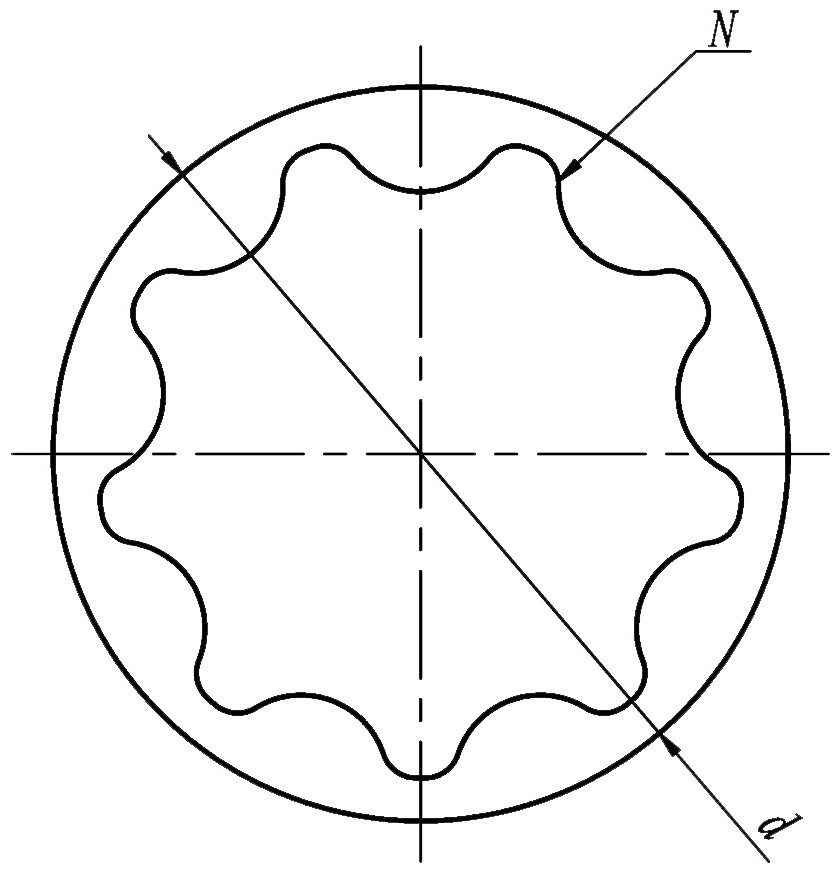
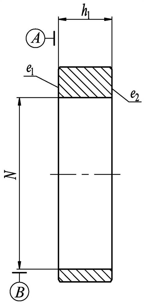
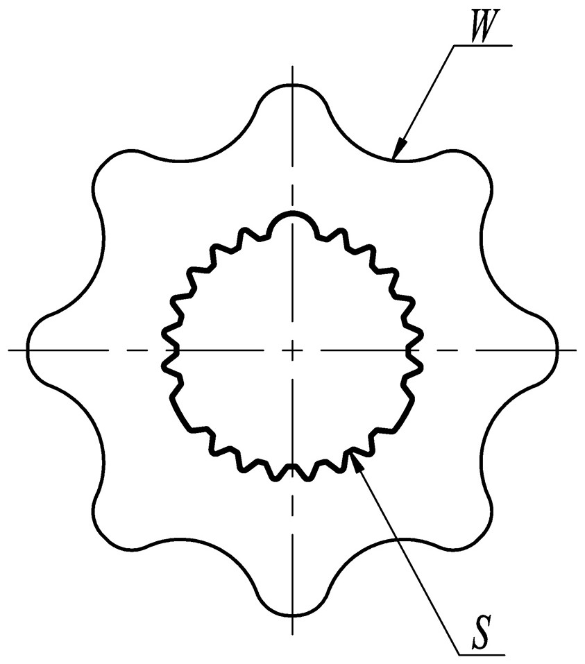
[0056] 2. Design the rotor struct...


PUM

PropertyMeasurementUnit
verticalityaaaaaaaaaa

Abstract

In a manufacturing method of an oil supplementing pump rotor based on powder metallurgy, rotor base body material components are modulated firstly, and non-directional deformation of tufftriding is effectively reduced in combination with a sintering process, so that the requirements on service life, economical efficiency and precision in the manufacturing process are met, then the end faces are ground simultaneously after the inner and outer rotors are paired, and consistency of product precision is effectively ensured; a self-designed flexible fastening centerless grinding tool is adopted, production efficiency is improved, and matching of the outer rotor and a pump shell is a base hole system, so that the matching precision requirement is met; meanwhile, a base body material is matched with a cold extrusion process and tufftriding is performed, so that base body hardness and strength of the part, in contact with a cycloid, of the inner and outer rotors are effectively improved; and an outer circle of the base body of the outer rotor is ground after tufftriding, so that the hardness and precision are improved, and meanwhile the self-lubricating characteristic of powder metallurgycompact holes is reserved.

Description

technical field [0001] The invention relates to the technical field of rotor manufacturing, in particular to a powder metallurgy-based manufacturing method for a charge pump rotor. Background technique [0002] In view of the structural characteristics and precision requirements of the internal and external rotors for conventional charge pumps, their mass production is generally obtained by powder metallurgy, and the finished products can be used after polishing. However, the working pressure of the conventional rotor charge pump is generally lower than 1.5bar, and the maximum pressure does not exceed 3bar; while the working pressure of the rotor charge pump applied to the servo variable control of the plunger pump exceeds 25bar for a long time, and the maximum pressure is 30bar. Under the action of high-pressure oil, the radial load of the inner rotor finally acts on the bearing through the drive shaft, and the radial load of the outer rotor acts on the side wall of the mat...

Claims


Application Information

Patent Timeline
Patent Type & Authority Applications(China)
IPC IPC(8): B22F5/00B22F3/10B22F3/24C22C38/08C22C38/12C22C38/16
CPCB22F5/00B22F3/1035B22F3/1007B22F3/24C22C38/08C22C38/12C22C38/16B22F2003/247B22F2999/00B22F2201/016
Inventor 张祝肖名涛吴斯灏
Owner SUZHOU SABO IND DESIGN
Features
  • R&D
  • Intellectual Property
  • Life Sciences
  • Materials
  • Tech Scout
  • Unparalleled Data Quality
  • Higher Quality Content
  • 60% Fewer Hallucinations
Learn More