Design scheme of direct-current countercurrent hole channel type heat exchanger/evaporator

A design scheme, heat exchanger technology, applied in nuclear power generation, reactors, reduction of greenhouse gases, etc., can solve the problems of broken heat transfer tubes, high cost, expensive equipment, etc., to achieve increased heat transfer area, small change The effect of thermal temperature difference and high heat transfer coefficient

Pending Publication Date: 2020-12-11
孟想
View PDF0 Cites 3 Cited by
  • Summary
  • Abstract
  • Description
  • Claims
  • Application Information

AI Technical Summary

Problems solved by technology

[0013] In the future, the pressurized water reactor nuclear power plant will also face the market requirements of ultra-supercritical power generation, and the U-tube shell-and-tube evaporator is technically unable to meet the heat transfer requirements of extreme high temperature or extreme pressure
Even in the face of the current working pressure and temperature of the primary circuit, since the material of the heat transfer tube cannot be used in step with the temperature field, the design and manufacture of the U-tube shell-and-tube evaporator is expensive, and the cost can be reduced by one-third. A Design Potential
[0014] Disadvantages: Whether it is a U-tube evaporator of a press

Method used


Image

  • Design scheme of direct-current countercurrent hole channel type heat exchanger/evaporator
  • Design scheme of direct-current countercurrent hole channel type heat exchanger/evaporator
  • Design scheme of direct-current countercurrent hole channel type heat exchanger/evaporator

Examples


Embodiment Construction

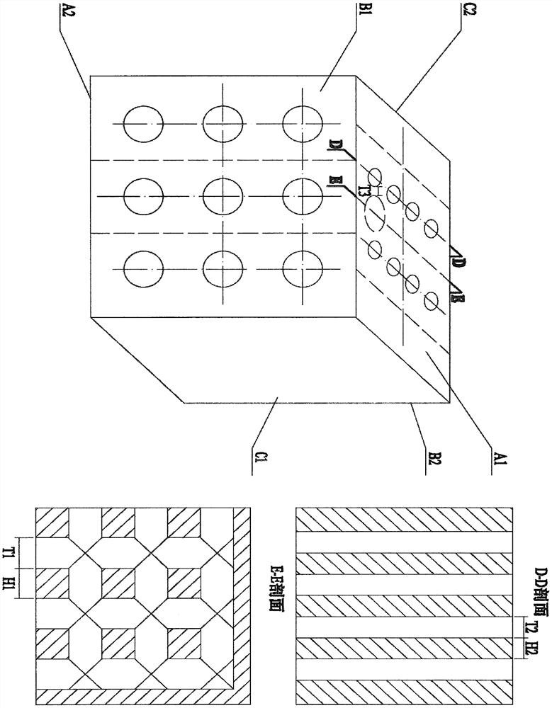
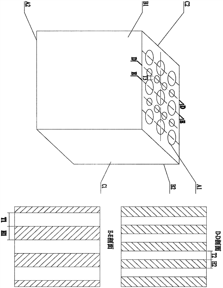
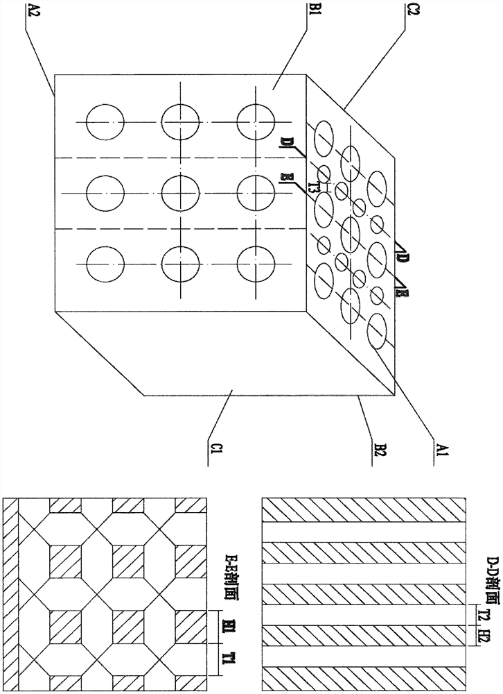
[0032] attached Figure 4It is an embodiment of the present invention in the application aspect of the steam generator / intermediate heat exchanger of a high-temperature gas-cooled reactor or an ultra-high-temperature gas-cooled reactor.

[0033] This embodiment is very suitable for the design of steam generators for high-temperature gas-cooled reactors with ultra-supercritical parameters for power generation. Ultra-high temperature superimposed ultra-high pressure technical parameters are the design difficulties and pain points of this embodiment. Under the high pressure design condition, the reliability of the heat transfer tube is not enough, and the accident of tube breakage and water loss is easy to occur. The working medium on the primary side of the high-temperature gas-cooled reactor is hot helium with a working pressure of 8 MPa and a working temperature of 750°C. ) flows inside, after deflection, it enters the primary side channel (H1) and secondary side channel (H2)...


PUM


Abstract

The invention discloses a design scheme of a direct-current countercurrent hole channel type heat exchanger/evaporator. According to the design scheme, specially-made circular, oval or long circular hole channels arranged in a heat exchange unit are used for direct-current countercurrent heat exchange, and heat exchange between hole channels of small holes or micro holes mainly based on multilayermetal heat conduction and heat convection is achieved, so that the heat transfer coefficient is high, the heat transfer energy efficiency is good, the heat stress is small, the heat transfer temperature difference is small, heat can be safely and stably transferred between the hole channels under the superhigh temperature and superhigh pressure conditions, high efficiency, simplicity, safety andreliability are achieved, and pipe breaking and water loss accidents of a shell-and-tube heat exchanger under the working conditions of ultra-high temperature and ultra-high pressure can be avoided; compared with a shell-and-tube heat exchanger with the same heat transfer capacity, the size, weight and manufacturing cost of the direct-current countercurrent pore channel type heat exchanger are reduced by more than one third, and heat transfer under the severe condition that the extremely high temperature is not higher than 1000 DEG C or the extremely high pressure is not higher than 1000 kg issupported; and the direct-current countercurrent hole channel type heat exchanger belongs to the technical field of heat transfer equipment and is mainly applied to the fields of nuclear power and thermal power, petrochemical engineering, chemical medicine, metallurgical hydrogen production and the like.

Description

[0001] (1) Technical field: [0002] The present invention is a new design scheme of heat exchanger / evaporator suitable for extreme high temperature or extremely high pressure. It utilizes the direct current countercurrent special channel set inside the heat exchange unit module to perform heat exchange, which is called direct current countercurrent channel heat exchanger / evaporator. device. The heat exchange between the direct current counterflow small holes or micropores, which is dominated by heat conduction and heat convection of heat transfer materials, has high heat transfer coefficient, small heat transfer temperature difference, and small thermal stress. Under certain conditions, the heat transfer between the channels can be carried out safely and stably. It has the characteristics of high efficiency, simplicity, safety and reliability. It belongs to the technical field of heat transfer equipment. [0003] (two) background technology: [0004] The nuclear steam generat...

Claims


Application Information

Patent Timeline
IPC IPC(8): G21C15/14G21C15/16G21C15/22
CPCG21C15/16G21C15/14G21C15/22Y02E30/30
Inventor 孟想
Owner 孟想
Why Eureka
Try Eureka