Combined filter material biological aerated filter system

A biological aerated filter and aeration system technology, applied in the field of combined filter material biological aerated filter system, can solve the problems of general nitrate nitrogen removal efficiency, insufficient stability of effluent SS, unsatisfactory backwash effect, etc. The effect of comprehensive economic benefits, saving backwashing time and improving backwashing efficiency

Pending Publication Date: 2020-12-15
杭州余杭净水有限公司 +1
View PDF0 Cites 1 Cited by
  • Summary
  • Abstract
  • Description
  • Claims
  • Application Information

AI Technical Summary

Problems solved by technology

[0003] In terms of water flow direction, there are two types of biological aerated filter: upflow type and downflow type. From the form of filter material, it can be divided into light filter material and heavy filter material, and it can be divided into nitrification filter material in terms of function. pool and denitrification filter, and each form of filter has its own advantages and disadvantages, such as the upflow denitrification filter with heavy filter material, the effluent SS effect of this form of filter is better, and the removal efficiency of nitrate nitrogen Generally, the backwashing effect is not ideal and it is easy to block, and the filter material will harden after a long service life; for example, the upflow light filter material nitrification filter has better water quality treatment effect, good backwashing effect, and the filter material is not easy to block , but the water SS is not stable enough, and often exceeds the standard

Method used


Image

  • Combined filter material biological aerated filter system
  • Combined filter material biological aerated filter system
  • Combined filter material biological aerated filter system

Examples


Embodiment

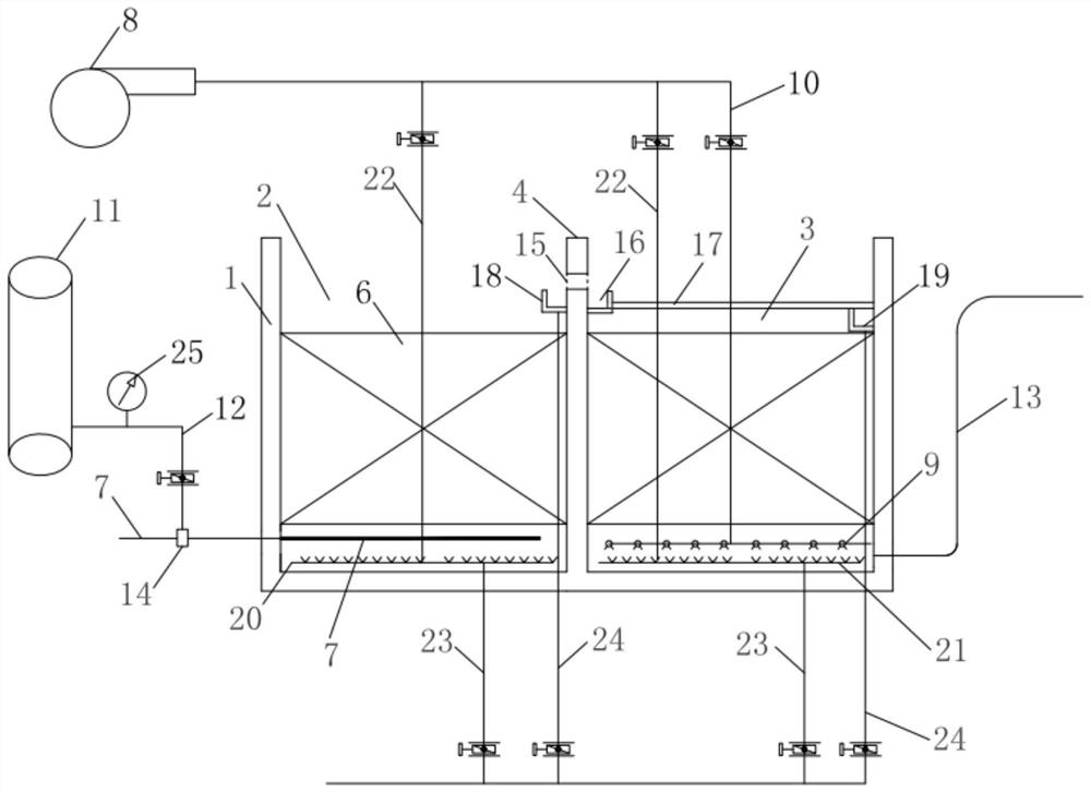
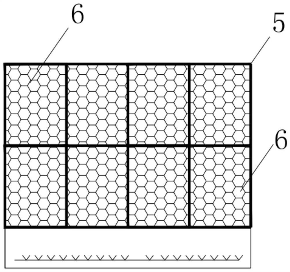
[0046] A combined filter material aerated biological filter system, such as figure 1 As shown, there are two reaction zones in total, which are non-aeration zone 2 and aeration zone 3 respectively, and the height of the filter material layer 6 in aeration zone 3 and non-aeration zone 2 is both 3.5m. The specifications of the filter material: the side length is 3cm, the porosity is above 85%, and the internal pore diameter of the filter material is between 1 and 1.5mm. Wherein the vertical direction is provided with 5 layers of filter material frames 5 in the non-aeration zone 2, the height of the lower two layers of single-layer filter material frames 5 is 1m, and the filling density of the filter material is 85%; the single-layer filter material frames of the upper three layers 5 The height is 0.5m, and the packing density of the filter material is 100%.

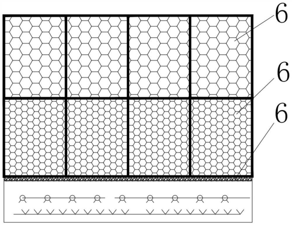
[0047] In the aeration area 3, there are three layers of filter material frames 5 in the vertical direction. The height ...


PUM

PropertyMeasurementUnit
pore sizeaaaaaaaaaa
thicknessaaaaaaaaaa
lengthaaaaaaaaaa

Abstract

The invention relates to the field of sewage treatment, in particular to a combined filter material biological aerated filter system, which comprises a filter body, an aeration system and a carbon source storage tank, and is characterized in that the filter body internally comprises a non-aeration area and an aeration area, and a retaining wall is arranged between the aeration area and the non-aeration area; a plurality of layers of filter material frames are fixed in the aeration area and the non-aeration area, and filter materials are filled in the filter material frames to form a filler layer; one side, close to the non-aeration area, of the filter tank body is communicated with a water inlet pipe, and one side, close to the aeration area, of the filter tank body is communicated with awater outlet pipe; the aeration system comprises air supply equipment and an aeration pipe arranged in the aeration area, and the air supply equipment is communicated with the aeration pipe through anair guide pipe; and a carbon source storage tank is communicated with the water inlet pipe through a carbon source feeding pipe. The system can improve the water quality treatment efficiency and effect, reduce the operation management difficulty, reduce the operation cost, simplify the structure in the pool and improve the maintenance efficiency, and has lower requirements on water inlet SS.

Description

【Technical field】 [0001] The invention relates to the field of sewage treatment, in particular to a combined filter material aerated biological filter system. 【Background technique】 [0002] Compared with the ordinary activated sludge method, the biological aerated filter has high organic load, small footprint (1 / 3 of the ordinary activated sludge method), less investment (saving about 30%), and no sludge bulking , High oxygen transmission efficiency, good effluent water quality, etc., but it has strict requirements on the SS of the influent (generally SS≤100mg / L, preferably SS≤60mg / L), so pretreatment is required for the influent. It is precisely because of the many advantages of the biological aerated filter that it has been widely used and promoted in the field of sewage treatment, especially the continuous improvement of the current sewage discharge standards, the application of the biological aerated filter in the field of advanced treatment is increasing universal. ...

Claims


Application Information

Patent Timeline
Patent Type & Authority Applications(China)
IPC IPC(8): C02F3/30C02F101/16C02F101/30
CPCC02F3/30C02F2101/163C02F2101/30C02F2209/08C02F2209/10C02F2305/06
Inventor 厉林聪吴益辉党勇杰吴凯张淼佳陆侨治李静张瑞
Owner 杭州余杭净水有限公司
Why Eureka
Try Eureka