Flue gas waste heat recycling and exchanging device and heat exchange method based on industrial energy conservation

A flue gas waste heat and heat exchange device technology, which is applied in the field of flue gas waste heat recovery, can solve problems such as wasting energy, polluting the environment, and harming the health of workers, and achieves the effect of preventing harm

Inactive Publication Date: 2020-12-15
李佳佳
View PDF7 Cites 3 Cited by
  • Summary
  • Abstract
  • Description
  • Claims
  • Application Information

AI Technical Summary

Problems solved by technology

[0002] At present, domestic industrial production generally uses fuel oil and coal combustion to obtain a large amount of heat required for production. During the production process, many energy-consuming equipment produce a large amount of smoke and discharge it into the atmosphere. Smoke has become the main way for general energy-consuming equipment to waste energy, such as Boiler smoke loss accounts for about 80% of boiler heat loss, while other equipment such as printing and dyeing industry setting machines, dryers, and metallurgical furnaces for metal smelting mainly consume energy through flue gas emissions, which pollute the environment and waste a lot of heat energy
[0003] At present, in the process of recovering flue gas waste heat, the flue gas will be mixed with a large number of sundries and particles, which will have a certain impact on the recovery of flue gas waste heat, and when the staff is performing heat exchange operations, it will It will cause certain harm to the health of the staff. For this reason, a flue gas waste heat recovery heat exchange device and heat exchange method based on industrial energy saving are proposed.

Method used


Image

  • Flue gas waste heat recycling and exchanging device and heat exchange method based on industrial energy conservation
  • Flue gas waste heat recycling and exchanging device and heat exchange method based on industrial energy conservation
  • Flue gas waste heat recycling and exchanging device and heat exchange method based on industrial energy conservation

Examples


Embodiment

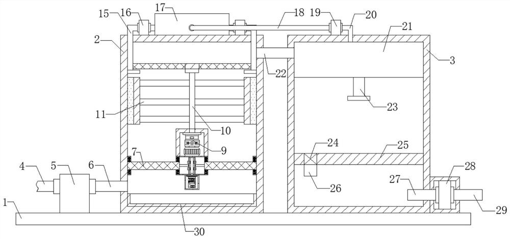
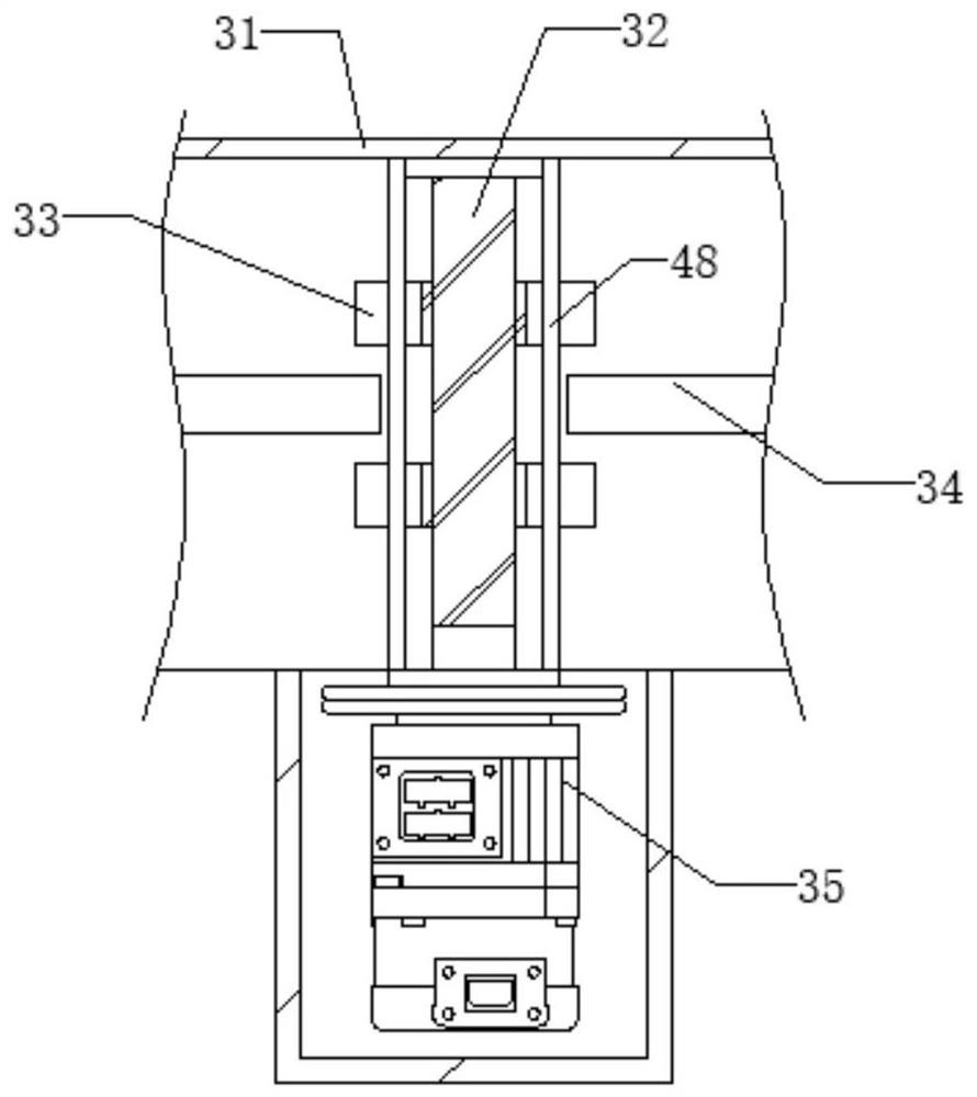
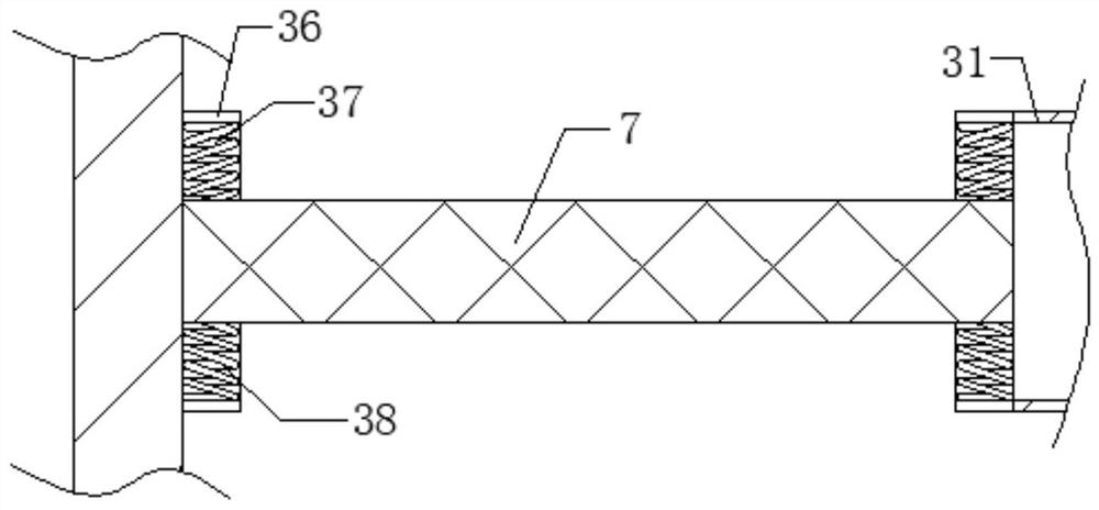
[0026] see Figure 1-5 , the present invention provides a technical solution: a flue gas waste heat recovery heat exchange device based on industrial energy saving, including a base 1, the upper surface of the base 1 is respectively welded with a first box body 2 and a second box body 3, the base 1 The first air pump 5 is installed on the upper surface, the air inlet of the first air pump 5 is connected with the first pipe body 4, the air outlet of the first air pump 5 is connected with the second pipe body 6, and one end of the second pipe body 6 is connected with the first pipe body 4. The inner wall of the box body 2, the inner wall of the first box body 2 is welded with a first housing 31, the inner bottom wall of the first housing 31 is equipped with a second motor 35, and the output shaft of the second motor 35 is fixedly connected with a screw thread Rod 32, the outer wall of threaded rod 32 is symmetrically threaded with two discs 33, the lower surface of first housing...


PUM


Abstract

The invention discloses a flue gas waste heat recycling and exchanging device and a heat exchange method based on industrial energy conservation. The flue gas waste heat recycling and exchanging device comprises a base; a first box body and a second box body are welded to the upper surface of the base respectively; a first air pump is installed on the upper surface of the base; flue gas is suckedinto the first box body; large foreign matter particles in the flue gas are filtered by a filter screen; meanwhile, the flue gas flows upwards, a first motor is started, and an output shaft of the first motor drives a rotating shaft to rotate, so that the rotating shaft drives stirring blades to rotate to form a centrifugal force, and thus the foreign matter particles in the flue gas move to the inner side wall of a first box body through the centrifugal force; the water in a water tank is pumped out through the first water pump and is sprayed out through a first L-shaped pipe to process the foreign matter particles, thus certain influence on recycling of flue gas waste heat is avoided; and when a worker conducts heat exchange operation, certain harm to the body health of the worker is prevented.

Description

technical field [0001] The invention relates to the technical field of flue gas waste heat recovery, in particular to a flue gas waste heat recovery heat exchange device and a heat exchange method based on industrial energy saving. Background technique [0002] At present, domestic industrial production generally uses fuel oil and coal combustion to obtain a large amount of heat required for production. During the production process, many energy-consuming equipment produce a large amount of smoke and discharge it into the atmosphere. Smoke has become the main way for general energy-consuming equipment to waste energy, such as Boiler smoke loss accounts for about 80% of boiler heat loss, while other equipment such as printing and dyeing industry setting machines, dryers, and metallurgical furnaces for metal smelting mainly consume energy through flue gas emissions, which pollute the environment and A lot of thermal energy is wasted. [0003] At present, in the process of rec...

Claims


Application Information

Patent Timeline
Patent Type & Authority Applications(China)
IPC IPC(8): F28D21/00F28F19/00F28F19/01B01D53/26F23J15/02F23J15/06
CPCB01D53/26F23J15/025F23J15/027F23J15/06F23J2217/10F23J2217/40F23J2217/50F28D21/0003F28F19/00F28F19/01Y02E20/30
Inventor 李佳佳
Owner 李佳佳
Why Eureka
Try Eureka