
Scrap removing device for mechanical drilling machine

A mechanical drilling and chip cleaning technology, which is applied in the field of machine tools, can solve problems such as material wear and drilling effects, and achieve the effects of improving stability, smooth rotation, and preventing shaking

Inactive Publication Date: 2020-12-18
王军
View PDF0 Cites 0 Cited by
  • Summary
  • Abstract
  • Description
  • Claims
  • Application Information

AI Technical Summary

Problems solved by technology

[0003] When the mechanical drilling machine drills the material, a large amount of debris will be generated at the drill bit. If the debris is not cleaned up in time, it may have a certain impact on the drilling and cause certain wear and tear on the material.

Method used


Image

  • Scrap removing device for mechanical drilling machine
  • Scrap removing device for mechanical drilling machine
  • Scrap removing device for mechanical drilling machine

Examples


Embodiment 1

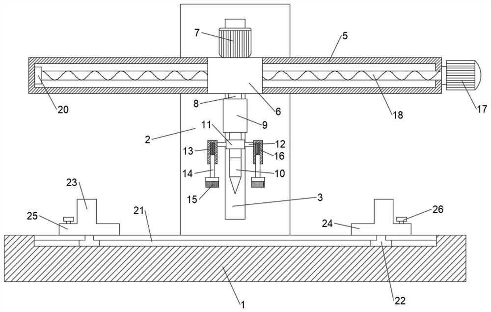
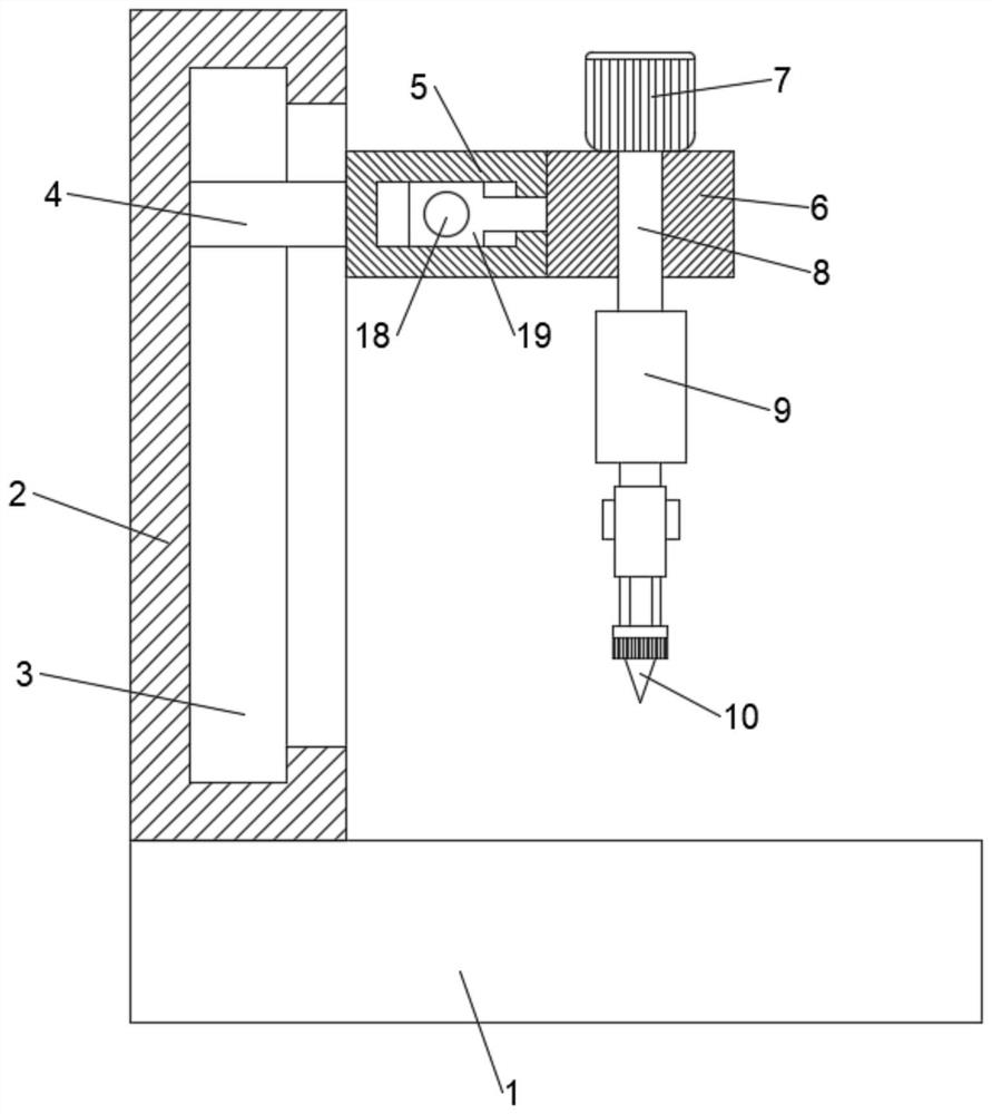
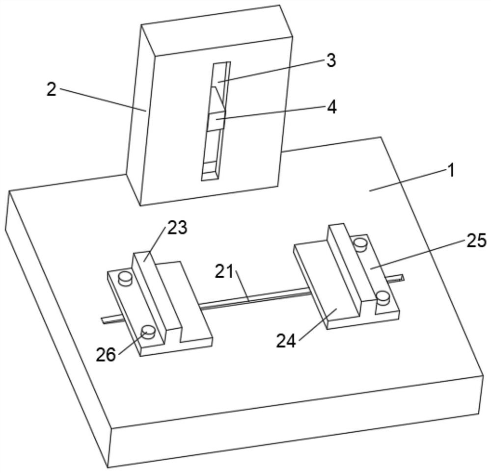
[0021] see Figure 1-3 , in an embodiment of the present invention, a chip cleaning device for a mechanical drilling machine includes a base 1, a bracket 2 is arranged on the upper end of the base 1, a groove 3 is arranged on the side wall of the bracket 2, and an electric slide is installed in the groove 3. block 4, the electric slider 4 is fixedly connected with a square frame 5, a mobile device is arranged in the square frame 5, the mobile device is fixedly connected with a connection seat 6, and the upper end of the connection seat 6 is provided with a motor one 7, and the output end of the motor one 7 is fixed A shaft rod 8 is connected, the shaft rod 8 runs through the connecting seat 6 and the lower end is fixedly connected with a telescopic rod 9, the end of the telescopic rod 9 is provided with a drill bit 10, and the side wall at the end of the telescopic rod 9 is provided with a chip removal device. 4 slide up and down in the groove 3 to adjust the height of the squ...

Embodiment 2

[0027] In order to improve the stability of the rotation of the screw 18, this embodiment is further improved on the basis of Embodiment 1. The improvement is: a shaft sleeve 20 is arranged on the inner left wall of the square frame 5, and the left end of the screw 18 is rotatably connected to the Inside the shaft sleeve 20, the stability of the screw rod 18 can be improved through the shaft sleeve 20, so that it can rotate more smoothly.

[0028] The working principle of this embodiment is: in order to improve the stability of the rotation of the screw rod 18, a shaft sleeve 20 is arranged on the inner left side wall of the square frame 5, and the left end of the screw rod 18 is connected in the shaft sleeve 20 in rotation, through the shaft sleeve 20 , can improve the stability of the screw rod 18, so that it can rotate more smoothly.

[0029]To sum up, by setting the chip removal device, the telescopic rod 9 also drives the chip removal device to rotate, and removes the deb...


PUM


Abstract

The invention discloses a scrap removing device for a mechanical drilling machine. The scrap removing device for the mechanical drilling machine comprises a base, a support is arranged at the upper end of the base, a groove is formed in the side wall of the support, an electric sliding block is installed in the groove in a sliding mode, the electric sliding block is fixedly connected with a squareframe, a moving device is arranged in the square frame, the moving device is fixedly connected with a connecting base, a first motor is arranged at the upper end of the connecting base, the output end of the first motor is fixedly connected with a shaft rod, the shaft rod penetrates through the connecting base, the lower end of the shaft rod is fixedly connected with a telescopic rod, a drill bitis arranged at the tail end of the telescopic rod, a scrap removing device is arranged on the side wall of the tail end of the telescopic rod, the electric sliding block slides up and down in the groove, so that the height of the square frame can be adjusted, the first motor is started, the drill bit is rotated, the telescopic rod is extended, and the material located below is drilled. Through the arrangement of the scrap removing device, the telescopic rod further drives the scrap removing device to rotate, scraps drilled out by the drill bit are removed, and the influence on material drilling is prevented.

Description

technical field [0001] The invention relates to the field of machine tools, in particular to a chip cleaning device for a mechanical drilling machine. Background technique [0002] Machining refers to the process of changing the shape or performance of a workpiece through a mechanical device. According to the difference in processing method, it can be divided into cutting processing and pressure processing. In the production process, the process of changing the shape, size, position and nature of the production object to make it a finished or semi-finished product is called a process. It is an essential part of the production process. The process can be divided into casting, forging, stamping, welding, machining, assembly and other processes. The mechanical manufacturing process generally refers to the sum of the machining process of parts and the assembly process of machines. Other processes are called auxiliary processes. Process, such as transportation, storage, power ...

Claims


Application Information

Patent Timeline
Patent Type & Authority Applications(China)
IPC IPC(8): B23B39/00B23Q11/00B23Q1/25B23Q3/06
CPCB23B39/00B23Q1/25B23Q3/06B23Q11/0042
Inventor 王军
Owner 王军
Learn More